


Rev. 1.00
435 of 576
January 28, 2022
32-Bit Arm
®
Cortex
®
-M0+ MCU
HT32F54231/HT32F54241/HT32F54243/HT32F54253
20 Inter-Integrated Circuit (I2C)
20 Inter-Integrated Circuit (I2C)
I
2
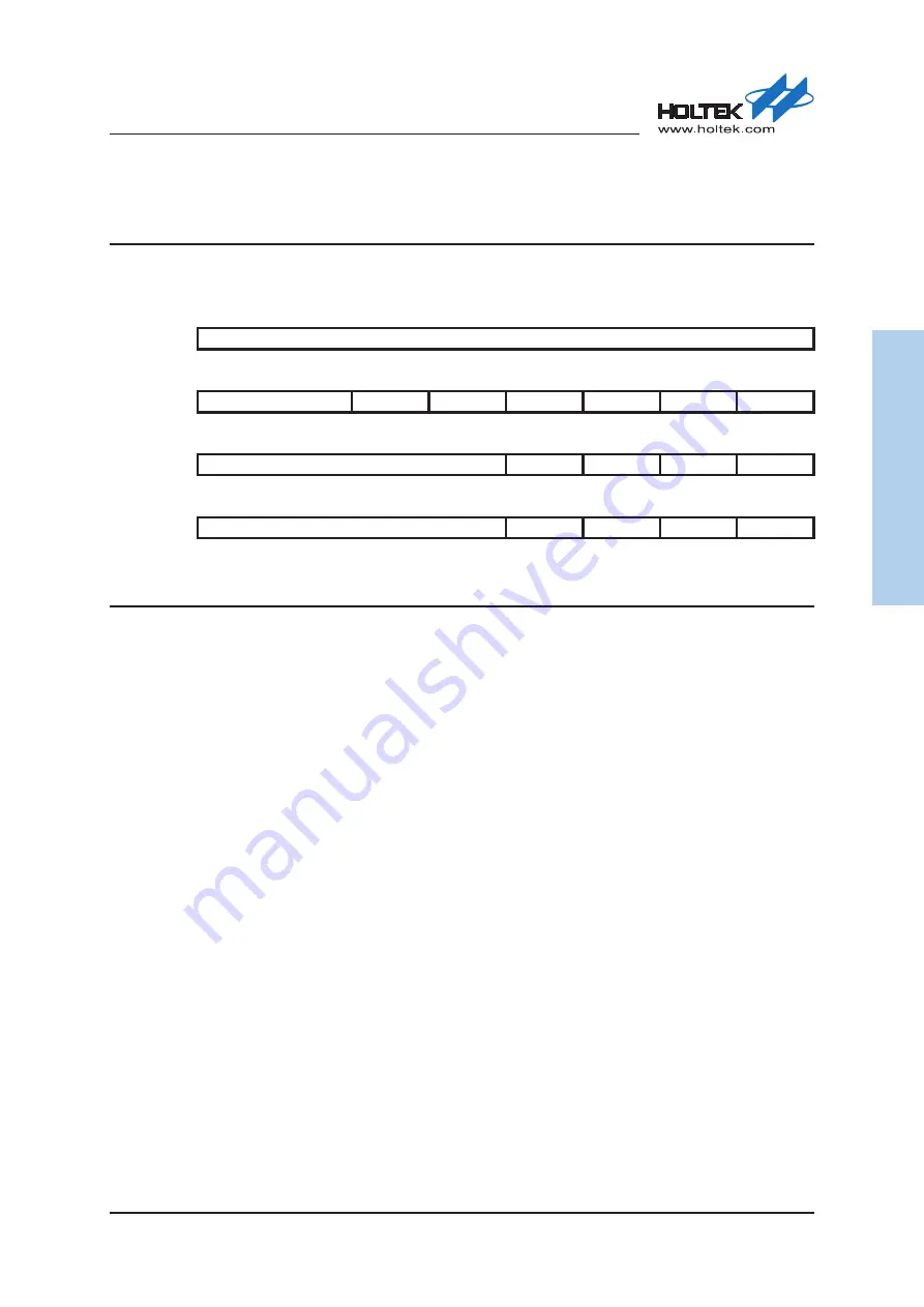
C Status Register – I2CSR
This register contains the I
2
C operation status.
Offset:
0x00C
Reset value: 0x0000_0000
31
30
29
28
27
26
25
24
Reserved
Type/Reset
23
22
21
20
19
18
17
16
Reserved
TXNRX
MASTER BUSBUSY
RXBF
TXDE
RXDNE
Type/Reset
RO 0 RO 0 RO 0 RO 0 RO 0 RO 0
15
14
13
12
11
10
9
8
Reserved
TOUTF
BUSERR RXNACK
ARBLOS
Type/Reset
WC 0 WC 0 WC 0 WC 0
7
6
5
4
3
2
1
0
Reserved
GCS
ADRS
STO
STA
Type/Reset
RC 0 RC 0 RC 0 RC 0
Bits
Field
Descriptions
[21]
TXNRX
Transmitter / Receiver Mode
0: Receiver mode
1: Transmitter mode
Read only bit.
[20]
MASTER
Master Mode
0: I
2
C is in the slave mode or idle
1: I
2
C is in the master mode
The I
2
C interface is switched as a master device on the I
2
C bus when the I2CTAR
register is assigned and the I
2
C bus is idle. The MASTER bit is cleared by hardware
when software disables the I
2
C bus by clearing the I2CEN bit to 0 or sends a STOP
condition to the I
2
C bus or the bus error is detected. This bit is set and cleared by
hardware and is a read only bit.
[19]
BUSBUSY
Bus Busy
0: I
2
C bus is idle
1: I
2
C bus is busy
The I
2
C interface hardware starts to detect the I
2
C bus status if the interface is
enabled by setting the I2CEN bit to 1. It is set to 1 when the SDA or SCL signal is
detected to have a logic low state and cleared when a STOP condition is detected.
[18]
RXBF
Buffer Full Flag in Receiver Mode
0: Data buffer is not full
1: Data buffer is full
This bit is set when the data register I2CDR has already stored a data byte and
meanwhile the data shift register also has been received a complete new data byte.
The RXBF bit is cleared by software reading the I2CDR register.