


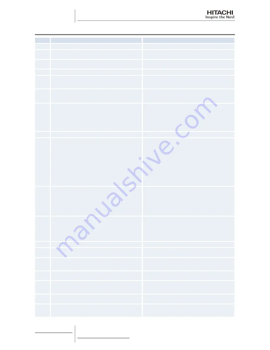
12.12 Pump-down method for replacing the compressor
No.
Procedure
Remarks
1
Turn off the main switch of the outdoor unit.
2
Remove the covers, the thermistor, the crankcase heater, the power
wirings, and other items according to the chapter 10.
Make sure that the terminal part of the detached power supply wires
is not exposed by the winding insulation tape and other items.
3
Attach the manifold to the check joint of the high pressure side and
the low-pressure side of the outdoor unit.
—
4
Turn on the main switch of the outdoor unit.
—
5
Set the exclusion of the compressor by setting the DSW so that a
broken compressor will not work. You can set the exclusion of the
compressor by setting the DSW1-4 in ON position.
—
6
The compressor replacing mode is performed:
•
The DSW1-4 on the outdoor unit PCB
→
ON (The cooling is run).
•
This operation is performed for up to a maximum of ten minutes.
•
If the inverter compressor is excluded, the operation starts after
three minutes.
7
The operation finishes when one of the following conditions occurs:
1
Ten minutes have passed and STP is displayed in seven
segments.
2
"08" is displayed in seven segments.
3
When Ps< 0.1 MPa is continued for one minute, in ten minutes
STP is displayed in seven seconds and the operation finishes.
•
The operation may finished when any of the conditions 1) to 3)
occurs.
8
Close the liquid stop valve completely.
To avoid the spillage of all the refrigerant if the check valve is broken.
9
Check for a leakage of the check valve on the discharge gas side:
•
DSW4-4 (enforced stoppage of the compressor)
→
ON, so that
the compressor will not run although the running command is
sent from the remote control switch.
•
Check that variation of Ps on the outdoor unit PCB is 17
seconds. Make sure that the Ps increase is within 0.03 Mpa in
two minutes after the Ps increase at the stoppage (during
approximately five minutes). Also make sure that Pd > Ps.
•
When you stop the compressor for replacing:
•
You can check the leakage of the check valve by means of the
Ps variation because the SVA opens so that the discharge gas
side of the inverter compressor can connect to the low-pressure
side.
•
0.03 MPa/2 minutes is within the permissible limits for the check
valve on the discharge gas side.
•
The leakage of the check valve may cause an incorrect brazing,
due to the gas pressure at the brazing of the discharge piping.
•
If the compressor-replacing mode is performed again, set the
DSW4-4 to OFF and keep the DSW4-4 at the OFF side during
ten minutes. Then, start according to the procedure No. 6.
10
Collect the refrigerant by means of the refrigerant collection:
•
Perform either A or B, depending on the process 10.
–
The leak rate at the process 10 is within the specification
→
Collect the refrigerant only at the low-pressure side.
–
The leak rate at the process 10 is greater than the
specification
→
Collect all the refrigerant of the outdoor unit
side by means of the machine.
•
The discharge of the refrigerant in the atmosphere is strictly
forbidden. Make sure that the refrigerant is collected by the
collector.
•
Keep a note of the quantity of the collected refrigerant.
11
After collecting the refrigerant, remove the change hose (collector
side) of the low-pressure side, so that the low-pressure side of the
refrigerant cycle will be the atmosphere pressure.
•
Make sure that there is no pressure increase of the low-pressure
sides after collecting the refrigerant.
•
Make sure that the refrigerant cycle is the atmosphere pressure.
Otherwise, problems such as the blowing of gas and the suction
of the cutting material) may occur when you are removing the
compressors.
12
Turn OFF the main switch of the outdoor unit.
—
13
Perform the replacement of the compressor and the change of the
refrigerant oil according to the section "replacing the compressor".
Make sure that you follow the instructions.
14
Perform the vacuum from the check joint of the low-pressure side.
If you collect the refrigerant only on the low-pressure side (A in 11).
You cannot perform the vacuum of the refrigerant from the check joint
of the high-pressure side.
15
Open the liquid stop valve and the gas stop valve completely when
you finish the vacuum.
—
16
Make sure that the power is turned OFF and attach the following
items: the power supply wire, the thermistor, the crankcase heater,
the 63H wiring, the panel and the nut).
—
17
Set the DSW back to the original setting. Make sure that all the
wirings to the compressor are connected correctly.
—
18
Recharge the refrigerant that is collected in the process by the stop
valve of the liquid side during the cooling at the TEST RUN mode.
If the replacement of the compressor takes more than two hours, an
additional change of the refrigerant is necessary. Additional change
= (replacing time – 2 hours) x 0.5 kg.
12 Maintenace notes
472
SMGB0060 rev. 1- 12/2010
Summary of Contents for RAS-10HRNM
Page 2: ......
Page 4: ...Index ii SMGB0060 rev 1 12 2010 ...
Page 56: ...2 Unit Installation 48 SMGB0060 rev 1 12 2010 ...
Page 117: ...RAS 4 6 HVRNM1E 4 Electrical Wiring 109 SMGB0060 rev 1 12 2010 4 ...
Page 118: ...RAS 4 6 HRNM1E 4 Electrical Wiring 110 SMGB0060 rev 1 12 2010 ...
Page 121: ...RAS 3HVRNS 4 Electrical Wiring 113 SMGB0060 rev 1 12 2010 4 ...
Page 122: ...RAS 4 6 HVRNS1E 4 Electrical Wiring 114 SMGB0060 rev 1 12 2010 ...
Page 123: ...RAS 8 10 HRNSE 4 Electrical Wiring 115 SMGB0060 rev 1 12 2010 4 ...
Page 124: ...4 Electrical Wiring 116 SMGB0060 rev 1 12 2010 ...
Page 145: ...Dry operation Continues in the next page 5 Control System 137 SMGB0060 rev 1 12 2010 5 ...
Page 147: ...Heating operation Continues in the next page 5 Control System 139 SMGB0060 rev 1 12 2010 5 ...
Page 148: ...5 Control System 140 SMGB0060 rev 1 12 2010 ...
Page 153: ...Activation for protection device control 5 Control System 145 SMGB0060 rev 1 12 2010 5 ...
Page 162: ...Activation for protection device control 5 Control System 154 SMGB0060 rev 1 12 2010 ...
Page 166: ...Preheating control of compressor 5 Control System 158 SMGB0060 rev 1 12 2010 ...
Page 168: ...5 Control System 160 SMGB0060 rev 1 12 2010 ...
Page 180: ...6 Optional functions 172 SMGB0060 rev 1 12 2010 ...
Page 224: ...8 Troubleshooting 216 SMGB0060 rev 1 12 2010 ...
Page 263: ...RAS 4 6 HVRNS1E 8 Troubleshooting 255 SMGB0060 rev 1 12 2010 8 ...
Page 264: ...RAS 8 10 HRNSE 8 Troubleshooting 256 SMGB0060 rev 1 12 2010 ...
Page 269: ...RAS 8 10 HRNSE 8 Troubleshooting 261 SMGB0060 rev 1 12 2010 8 ...
Page 337: ...RAS 4 6 HVRNM1E Cycle and structural parts 9 Spare Parts 329 SMGB0060 rev 1 12 2010 9 ...
Page 340: ...RAS 4 6 HRNM1E Cycle and structural parts 9 Spare Parts 332 SMGB0060 rev 1 12 2010 ...
Page 342: ... Electrical parts 9 Spare Parts 334 SMGB0060 rev 1 12 2010 ...
Page 354: ... Electrical parts 9 Spare Parts 346 SMGB0060 rev 1 12 2010 ...
Page 356: ...RAS 8 10 HRNSE Cycle and structural 9 Spare Parts 348 SMGB0060 rev 1 12 2010 ...
Page 359: ... Electrical parts 9 Spare Parts 351 SMGB0060 rev 1 12 2010 9 ...
Page 440: ...10 Servicing 432 SMGB0060 rev 1 12 2010 ...
Page 464: ...11 Electrical checks of main parts 456 SMGB0060 rev 1 12 2010 ...
Page 481: ......