Hitachi RAS-10HRNM Service Manual Download Page 458

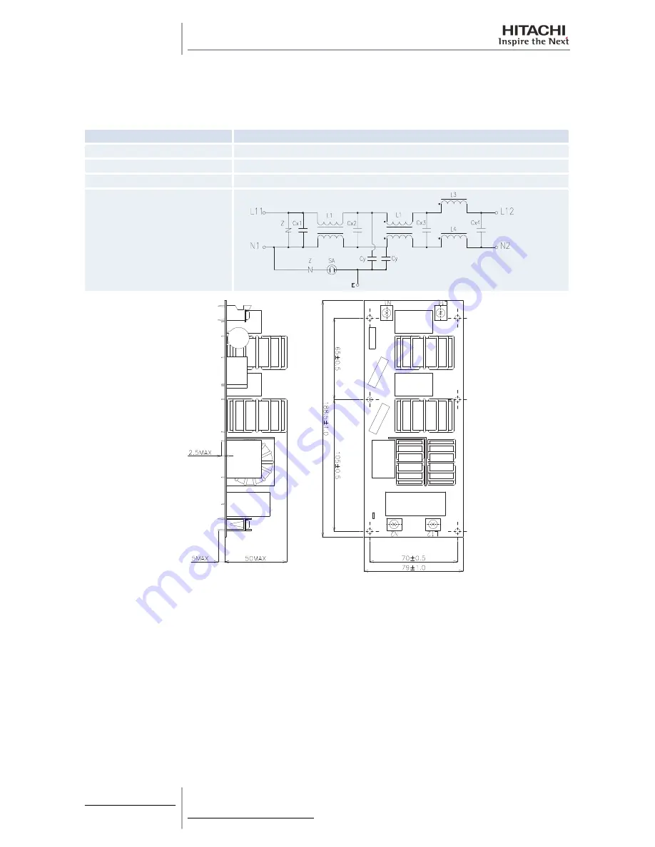
11.5.2 Noise filter for ES Series

The noise filter decreases the leakage of noise made by the inverter to the power supply side. Terminals indicated with
“LOAD” are connected to the inverter side and terminals indicated with “LINE” to the power supply side.

RAS-(4-6)HVRNS1E (230V/50Hz)

Items

Specifications

Model

LFB-14930-3M

Rated current

AC230V 30 A

Permissible temperature range.

-25 ºC to 85 ºC

Circuit diagram

Load

Line

11 Electrical checks of

main parts

450

SMGB0060 rev. 1- 12/2010

Summary of Contents for RAS-10HRNM

Page 1: ...UTOPIA DC INVERTER IVX ES SERIES H V RN 1 S 1 E H V RNM 1 E Service Manual RAS 3 6 HVRNM 1 E RAS 4 12 HRNM 1 E RAS 2 3 HVRN 1 E S RAS 4 6 HVRNS1E RAS 8 10 HRNSE ...

Page 2: ......

Page 3: ...ral information 1 Unit Installation 2 Piping work and refrigerant charge 3 Electrical Wiring 4 Control System 5 Optional functions 6 Test Run 7 Troubleshooting 8 Spare Parts 9 Servicing 10 Electrical checks of main parts 11 Maintenace notes 12 ...

Page 4: ...Index ii SMGB0060 rev 1 12 2010 ...

Page 5: ... RAS 4 10 H V RNS 1 E 22 2 6 2 Place provision only for RAS 2 3 HVRN 1 E S 25 2 7 Optional parts and installation 28 2 7 1 Optional parts and installation for RAS 2 3 HVRN 1 E S 28 2 7 2 Optional parts and installation RAS 3HVRNME RAS 4 6 HVRNS1E 33 2 7 3 Optional parts and installation RAS 4 6 H V RNM1E RAS 8 10 HRNSE 37 2 7 4 Optional parts and installation RAS 8 12 HRNM 42 3 Piping work and ref...

Page 6: ...sizes for ES Series 97 4 5 3 H LINK System 98 4 6 Electrical wiring diagrams 108 4 6 1 Electrical wiring diagrams for IVX Series 108 4 6 2 Electrical wiring diagrams for ES Series 112 5 Control System 117 5 1 Device control system 118 5 1 1 Device control system for IVX Series 118 5 1 2 Device control system for ES Series 120 5 2 Outdoor units PCB 122 5 2 1 Outdoor units PCB for IVX Series 122 5 2...

Page 7: ...3 Troubleshooting by means of the 7 segment display 290 8 2 4 Troubleshooting by means of the flashing alarm LEDs for RPK FSNM 294 8 2 5 Cause of inverter stoppage 295 8 3 Procedure for checking each main part 299 8 3 1 Self checking procedure of PCB by means of the Remote Control Switch 299 8 3 2 Self checking of the remote control switch 301 8 3 3 Self Checking procedure of the Indoor Unit PCB o...

Page 8: ...oling performance when a long piping is applied 460 12 4 Abnormally high operation sound in the ceiling type indoor unit 461 12 5 Alarm code 31 462 12 6 Not cooling well due to insufficient installation space for the outdoor unit 463 12 7 Caution with the refrigerant leakage 464 12 7 1 Maximum permissible concentration of the HCFC gas 464 12 7 2 Calculation of the refrigerant concentration 464 12 ...

Page 9: ...onment friendly units 2 1 2 Safety 3 1 2 1 Applied symbols 3 1 3 Product guide 4 1 3 1 Classification of IVX series outdoor unit models 4 1 3 2 Classification of ES series outdoor unit models 4 1 3 3 Product guide Outdoor units 5 1 3 4 Accessory code list 6 1 General information 1 SMGB0060 rev 1 12 2010 1 ...

Page 10: ...pite this printing errors cannot be controlled by HITACHI and are not its responsibility As a result some of the images or data used to illustrate this document may not refer to specific models No claims will be accepted based on the data illustrations and descriptions included in this manual No type of modification must be made to the equipment without prior written authorisation from the manufac...

Page 11: ... taking these instructions into account could lead to serious very serious or even fatal injuries to you and others in the proximities of the unit In the texts following the danger symbol you can also find information on safe procedures during unit installation CAUTION The text following this symbol contains information and instructions relating directly to your safety and physical wellbeing Not t...

Page 12: ...efrigerant M High Efficiency Series E Made in Europe Made in Japan XXX XX H V R N M 1 X 1 3 2 Classification of ES series outdoor unit models Unit type outdoor unit RAS Position separating hyphen fixed Capacity HP 2 2 5 3 4 5 6 8 10 H Heat Pump V Single Phase 1 R Inverter system N R410A refrigerant S Eco Small Series E Made in Europe Made in Japan XXX XX H V R N S 1 X 1 General information 4 SMGB0...

Page 13: ...assification for each unit model type power and series in Classification of IVX series outdoor unit models see on page 4 ES series outdoor units Outdoor Units ES Single Fase 1 Three Fase 3 HVRN 1 E S HVRNS1E HRNSE Unit Code Unit Code Unit Code RAS 2HVRN1E 60288093 RAS 4HVRNS1E 7E306007 RAS 8HRNSE 7E314110 RAS 2 5HVRN1 60288094 RAS 5HVRNS1E 7E306008 RAS 10HRNSE 7E314111 RAS 3HVRNS 60288101 RAS 6HVR...

Page 14: ...cal Catalogue Name Description Code Figure AG 335A Air outlet diffuser one for each fan 60291431 Images not available WSP 335A Wind guard 60291432 ASG NP335F Snow guard one for each fan 60291433 ASG NP335B Snow guard one for each fan 60291434 ASG NP335L Snow guard 60291435 DBS 26 Drain discharge connection 60299192 1 General information 6 SMGB0060 rev 1 12 2010 ...

Page 15: ...20 2 6 Place provision 22 2 6 1 Place provision for RAS 3 12 H V RNM 1 E and RAS 4 10 H V RNS 1 E 22 2 6 2 Place provision only for RAS 2 3 HVRN 1 E S 25 2 7 Optional parts and installation 28 2 7 1 Optional parts and installation for RAS 2 3 HVRN 1 E S 28 2 7 2 Optional parts and installation RAS 3HVRNME RAS 4 6 HVRNS1E 33 2 7 3 Optional parts and installation RAS 4 6 H V RNM1E RAS 8 10 HRNSE 37 ...

Page 16: ...inium fins have very sharp edges Pay attention to the fins in order to avoid injury Do not install the indoor units in a flammable environment to avoid a fire or an explosion Check to ensure that the ceiling slab is strong enough If not strong enough the indoor unit may fall down on you Do not install the indoor units outdoor unit remote control switch and cable within approximately 3 meters from ...

Page 17: ...2 3 HVRN 1 E S RAS 8 12 HRNM RAS 4 6 HVRNS1E RAS 8 10 HRNSE 1 A B C D 1 A B C D 1 Wire rope A Over 60º B 0 7 to 1 0 m C Do not remove the plastic band or the corrugate paper frame D Pass the wire ropes through each lifting hole in the wooden base as shown CAUTION Lift the outdoor unit in its factory packaging with 2 wire ropes For safety reasons ensure that the outdoor unit is lifted smoothly and ...

Page 18: ...sons are needed to move the unit RAS 2 3 HVRN 1 E S a 515 mm b 180 mm h 275 mm 1 RAS 3HVRNME a 590 mm b 185 mm h 370 mm 1 RAS 4 6 HVRNS1E For 4 HP a 635 mm b 180 mm h 335 mm For 5 6 HP a 630 mm b 190 mm h 360 mm RAS 4 6 H V RNM1E a 615 mm b 190 mm h 570 mm 1 RAS 8 12 HRNM a 615 mm b 190 mm h 570 mm RAS 8 10 HRNSE For 8 HP a 325 mm b 206 mm h 565 mm For 10HP a 325 mm b 213 mm h 585 mm 1 Center of g...

Page 19: ...nit NOTE If any of these accessories are not packed with the unit please contact your dealer Accessory Appearance Quantity RAS 8HRNM RAS 10HRNM RAS 12HRNM Gasket 1 1 1 Pipe flange for refrigerant gas piping 1 1 1 Ring core 1 1 1 Cable tie 1 1 1 Compressed sheet 1 1 1 2 Unit Installation 11 SMGB0060 rev 1 12 2010 2 ...

Page 20: ...ed with be 400 or greater Ensure 250 mm or more of the side space on the pipe cover side Upper Side Blocked Single Installation Multiple Installation Two units or more Pipe Cover Pipe Cover Fifteen mm of space is acceptable for one of the lateral sides Ensure 250 mm or more of the side space on the pipe cover side Allow 250 mm of service space between units Leave open both right and left sides Ens...

Page 21: ... Pipe Cover Be sure to use the fan direction guide Leave open both right and left sides Be sure to use the fan direction guide Allow 250 mm of service space between units Serial installation allowed up to two units Leave open both right and left sides The length A is as show in the following table L A 0 L 1 2H 100 or greater 1 2H L H 200 or greater When L H use a base for outdoor unit to make L H ...

Page 22: ...side space on the pipe cover side Ensure 250 mm or more of the side space on the pipe cover side Upper Side Blocked Pipe Cover Pipe Cover Ensure 250 mm or more of the side space on the pipe cover side Ensure 250 mm or more of the side space on the pipe cover side 2 Unit Installation 14 SMGB0060 rev 1 12 2010 ...

Page 23: ...Ensure 250 mm or more of the side space on the pipe cover side Allow 400 mm of service space above the top board Be sure to use the fan direction guide Allow 250 mm of service space between units Serial side way installation allowed but leave open both right and left sides Close the part A not to allow the outlet air bypassed Install to avoid the drain water from upper unit falling on the lower un...

Page 24: ...rection guide Allow 100 mm of space between units Leave open both right and left sides When subject to direct sunlight on the back wall ensure the length marked with be 500 or greater Upper Side Blocked Single Installation Multiple Installation Two units or more 100 mm or more of the side space is acceptable on the service cover side Dimensions in shows numbers especially for IVX 4 10 HP and ES 8 ...

Page 25: ...be open Be sure to use the fan direction guide Leave open both right and left sides Be sure to use the fan direction guide Allow 100 mm of space between units Serial installation allowed up to two units Leave open both right and left sides The length A is as shown in the following table L A 0 L 1 2H 200 1 2H L H 300 When L H use a base for outdoor unit to make L H Close the base not to allow the o...

Page 26: ...ow the outlet air bypassed Install to avoid the drain water from upper unit falling on the lower unit Upper Side Blocked Single Installation Multiple Installation Be sure to use the fan direction guide Close the part A not to allow the outlet air bypassed Install to avoid the drain water from upper unit falling on the lower unit Be sure to use the fan direction guide Allow 100 mm of space between ...

Page 27: ...open both right and left sides The length A is as shown in the following table L A 0 L 1 2H 200 1 2H L H 300 NOTE When L H use a base for outdoor unit to make L H Close the base not to allow the outlet air bypassed Be sure to use the fan direction guide in order to ensure the length marked with 2 Unit Installation 19 SMGB0060 rev 1 12 2010 2 ...

Page 28: ... open Around sides are open with obstacles above Around sides are closed Around sides are open with obstacles above Multiple installation Around sides are open Around sides are open with obstacles above Multi Row 2 Unit Installation 20 SMGB0060 rev 1 12 2010 ...

Page 29: ... concret height L A B 0 L 1 2 H 600 or more 300 or more 1 2H L H In this situation ensure that the base is closed and does not allow the airflow to short circuit In each case install the outdoor unit so that the discharge flow is not short circuited When the installation dimension results the one marked with an mount the air flow guide 2 Unit Installation 21 SMGB0060 rev 1 12 2010 2 ...

Page 30: ...de 100 x Depth 150 6 Drainage 7 Vibration proof rubber NOTE Space for downward piping space Anchor bolt location in case of RAS 8 12 HRNM 1 The whole base of the outdoor unit should be installed on a foundation When using vibration proof material it should also be positioned in the same place When installing the outdoor unit on a fieldsupplied frame use metal plates to adjust the frame width for s...

Page 31: ...unit to the wall 1 Fix the unit onto the wall as shown in the figures Field supplied bracket 2 Secure the foundation to avoid noise and warping 3 To avoid vibrations transferring to the building use a rubber mat RAS 3HVRNME RAS 4 6 H V RNM1E RAS 4 6 HVRNS1E RAS 8 12 HRNM RAS 8 10 HRNSE A 1 2 2 1 1 Rubber material 2 Fixing plate NOTE In RAS 8 12 HRNM are 110 mm Model RAS 3HVRNME RAS 4 6 HVRNS1E RAS...

Page 32: ...aller CAUTION Follow these installation procedures carefully The installation must be done so as to ensure that the outdoor unit does not lean vibrate make a noise or fall in the event of strong gusts of wind or earthquakes Calculate the resistance to vibration caused by earthquakes to guarantee that the installation is sturdy enough to prevent falls Secure the unit with cables field supplied when...

Page 33: ... 6 HVRNS1E RAS 8 12 HRNM RAS 8 10 HRNSE CAUTION An excessively strong wind blowing against the outlet of the outdoor unit may cause reverse rotation and damage to the fan motor 2 6 2 Place provision only for RAS 2 3 HVRN 1 E S 1 Secure the outdoor unit with the anchor 1 Base of outdoor unit 2 Nut 3 Special washer M12 4 Anchor bolts 5 Filled mortar 6 Concrete A Max 17 mm Fix the outdoor unit to the...

Page 34: ...30x80 2 Drain hole 3 30x80 3 Front side 5 The whole of the base of the outdoor unit should be installed on a foundation When using vibration proof mat it should also be positioned the same way When installing the outdoor unit on a field supplied frame use metal plates to adjust the frame width for stable installation as shown in Figure 1 Outdoor unit is unstable 2 Frame 3 Outdoor unit is stable 4 ...

Page 35: ...he product 1 Choose a location where the outlet or inlet side of the product will not be exposed to strong wind 2 When the outlet is exposed to strong wind Direct strong wind may cause lack of air flow and adversely affect to normal function CAUTION Excessive strong wind against the outdoor unit outlet may cause inverse rotation and damage the fan and motor 2 Unit Installation 27 SMGB0060 rev 1 12...

Page 36: ...uide Air discharge direction Upward downward left right Material Weather proof polypropylene resin Color Gray Weight 1 4 kg Accessories Fixing screw 4x M5 SUS x 12 4x M5 SUS x 30 Installation manual Self screw 2x M4 x 13 Installation restriction Wind Guard or Snow protection hood is not available to install with air flow guide Guard net is available to be installed together Attaching example of ai...

Page 37: ...ssories 5 Air flow guide Service space In case of upward air discharge In case of right and left sides air discharge enough space for air discharge is required The downward air discharge is also available In such case install the base under the unit to secure enough space for air discharge In case of serial units installation air discharge should be upward 1 Min 150 mm 2 Outdoor unit 3 Air flow gu...

Page 38: ...h the air flow guide to the air discharge grille with four 4 screws supplied The fixing holes are located at 4 positions on the grille Screw tightening torque 2 4 3 1 N m Do not remove the air discharge grille for air flow guide installation CAUTION If the air guide is installed without discharge grille it may cause injury due to rotating fan Two windguard covers installation 1 Air discharge grill...

Page 39: ...hood Nº Part name Quantity 1 Right side plate 1 2 Left side plate 1 3 Upper front panel Upside 1 4 Upper front panel Downside 1 5 Hole for safety wire rope to prevent overturning 6 Fixing screw Accessories Left suction hood Nº Part name Quantity 1 Right side plate 1 2 Left side plate 1 3 Upper front panel Upside 1 4 Upper front panel Downside 1 1 2 3 4 5 1 2 3 4 2 Unit Installation 31 SMGB0060 rev...

Page 40: ...heet Iron Stainless NSSC180 Bonderized steel sheet Iron Stainless NSSC180 Color Gray 1 0Y8 5 0 5 or approximation Gray 1 0Y8 5 0 5 or approximation Gray 1 0Y8 5 0 5 or approximation Weight 3 kg 6 kg 3 kg Assembling Knockingdown parts assembled at field Components Hood For air discharge part x 1 For rear side air intake x 1 For left side air intake x 1 Unit Fixing screw 4 M5x12 tapping screw 5 M5x1...

Page 41: ...2 Air flow guide Air discharge direction Upward downward left right Material Weather proof polypropylene resin Color Gray Weight 1 9 kg Accessories Fixing screw x 4 M5 SUS x 20 Installation manual Installation restriction Wind Guard or Snow protection hood is not available to install with air flow guide Guard net is available to be installed together Attaching example of air flow guide Attach the ...

Page 42: ...ir discharge In case of serial units installation air discharge should be upward 1 Min 200 mm 2 Outdoor unit 3 Air flow guide 4 Passage side Wind guard Specifications Model WSP 335A Quantity 1per unit 1 1 2 2 2 2 3 1 Mounting dimension 2 Air flow 3 3 4xØ7 Material Galvanized sheet metal baked painting Color Gray 1 0Y8 5 0 5 Weight 5 5 kg Accessories Fixing screw x 4 M5 SUS x 12 Installation manual...

Page 43: ... fan One windguard cover installation 1 Air discharge grille 2 Wind guard 3 Air discharge grille 4 Outdoor unit 5 M5 fixing screw x4 Accessories Service space Both sides of the outdoor unit should be open No obstacles should be placed in the air discharge side 1 Min 200 mm 2 Outdoor unit 3 Wind guard Snow protection hood Air discharge hood Nº Part name Quantity 1 Right side plate 1 2 Left side pla...

Page 44: ...eft side plate 1 3 Front panel Upside 1 4 Front panel Downside 1 5 Fixing hole x 2 6 Fixing screw Accessories A Enlarged view of A Fixing Hole Attaching example of snow protection hood 1 1 1 1 1 2 3 4 A B C 5 6 7 1 Fixing screw Accessories 2 Rear suction hood 3 Wire rope Optional For overturning protection 4 Air discharge grille 5 Left suction hood 6 Air discharge hood A Left side B Front side C R...

Page 45: ...4 tapping screw 6 M5x12 tapping screw Unit Fixing screw SUS 6 M5x12 tapping screw 6 M5x14 12 M5x12 tapping screw 12 M5x14 10 M5x12 tapping screw 10 M5x14 Installation manual Installation restriction Installation with Guard net or Wind guard is not available Installation with Guard net is not available Safety wire rope for overturning prevention optional parts ASG SW20A 2 7 3 Optional parts and ins...

Page 46: ...tening torque 2 4 3 1 N m Do not remove the air discharge grille for air flow guide installation CAUTION If the air guide is installed without discharge grille it may cause injury due to rotating fan Two flow guides installation 1 Air discharge grille 2 Air flow 3 Air flow guide see the note 4 Outdoor Unit 5 M5 fixing screw x4 Accessories NOTE Air flow direction of both air flow guides should be t...

Page 47: ...all with Wind guard Attaching example of air wind guard Attach the air flow guide to the air discharge grille with four 4 screws supplied The fixing holes are located at 4 positions on the grille Screw tightening torque 2 4 3 1 N m Do not remove the air discharge grille for air flow guide installation CAUTION If the air guide is installed without discharge grille it may cause injury due to rotatin...

Page 48: ...to prevent overturning Rear suction hood Nº Part name Quantity 1 Right side plate 1 2 Left side plate 1 3 Upper front panel Upside 1 4 Upper front panel Downside 1 5 Fixing screw Accessories 6 Hole for safety wire rope to prevent overturning Left suction hood Nº Part name Quantity 1 Right side plate 1 2 Left side plate 1 3 Front panel Upside 1 4 Front panel Downside 1 5 Fixing hole x 2 6 Fixing sc...

Page 49: ...ood 2 Fixing screw Accessories 3 Rear suction hood Upper side 4 Wire rope Optional For overturning protection 5 Rear suction hood Lower side 6 Air discharge hood 7 Air discharge grille 8 Air discharge grille A Front side B Left side C Rear side 2 Unit Installation 41 SMGB0060 rev 1 12 2010 2 ...

Page 50: ...M5x14 tapping screw 8 M5x12 tapping screw Fixing screw SUS 6 M5x14 tapping screw 6 M5x14 24 M5x14 tapping screw 24 M5x14 12 M5x12 tapping screw 12 M5x14 Installation manual Installation restriction Installation with Guard net Wind guard or Air flow guide is not available Installation with Guard net is not available Safety wire rope for overturning prevention optional parts ASG SW20A 2 7 4 Optional...

Page 51: ...ng torque 2 4 3 1 N m Do not remove the air discharge grille for air flow guide installation CAUTION If the air guide is installed without discharge grille it may cause injury due to rotating fan Two flow guides installation 1 Air discharge grille 2 Air flow 3 Air flow guide see the note 4 Outdoor Unit 5 M5 fixing screw x4 Accessories NOTE Air flow direction of both air flow guides should be the s...

Page 52: ...tall with Wind guard Attaching example of air wind guard Attach the air flow guide to the air discharge grille with four 4 screws supplied The fixing holes are located at 4 positions on the grille Screw tightening torque 2 4 3 1 N m Do not remove the air discharge grille for air flow guide installation CAUTION If the air guide is installed without discharge grille it may cause injury due to rotati...

Page 53: ...Left side plate 1 3 Front panel 1 4 Stay 4 5 Fixing screw Accessories 6 Hole for safety wire rope to prevent overturning Rear suction hood Nº Part name Quantity 1 Right side plate 1 2 Left side plate 1 3 Upper front panel Downside 1 4 Upper front panel Upside 1 5 Fixing screw Accessories 6 Hole for safety wire rope to prevent overturning 1 2 3 1 2 3 4 5 6 2 1 3 4 5 6 320 320 888 868 250 270 60 2 U...

Page 54: ...ection hood 1 2 2 2 2 2 A B C 3 4 5 5 6 6 7 8 1100 1650 390 1 Left suction hood 2 Fixing screw Accessories 3 Rear suction hood Upper side 4 Wire rope Optional For overturning protection 5 Air discharge hood 6 Air discharge grille 7 Rear suction hood Lower side 8 Outdoor unit A Front side A 316 A 1587 250 3 4 1 2 6 230 5 347 330 330 330 235 296 8 5 Ø15 R 7 A 2 Unit Installation 46 SMGB0060 rev 1 12...

Page 55: ... Weight 3 kg 14 kg 8 kg Assembling Knockingdown parts assembled at field Components Hood For air discherge part x 1 For rear side air intake x 1 Upper side x 1 lowe side x 1 For left side air intake x 1 Fixing screw 4x M5x12 l tapping screw 10x M5x14 l tapping screw 8x M5x12 l tapping screw Fixing screw SUS 6x M5x12 l tapping screw 6x M5x14 l 24x M5x14 l tapping screw 24x M5x14l 14x M5x12 tapping ...

Page 56: ...2 Unit Installation 48 SMGB0060 rev 1 12 2010 ...

Page 57: ... 8 Pump down refrigerant 59 3 3 Outdoor Units IVX Series 60 3 3 1 Piping connection 60 3 3 2 Refrigerant piping length 65 3 3 3 Refrigerant piping selection 66 3 3 4 Twin and triple system installation 67 3 3 5 Drain discharging boss 68 3 4 Outdoor Units ES Series 70 3 4 1 Piping connection 70 3 4 2 Refrigerant piping length 75 3 4 3 Refrigerant piping selection 76 3 4 4 Twin and triple system ins...

Page 58: ...ain piping 2 Pitch of 4 1 25 to 1 1 100 3 Drain piping connection The drain pipe will require insulation if it is installed in a location where the ambient humidity may condensate on the drain pipe outer surface This condensation could drop and cause damage The insulation for the drain pipe must be selected in order to ensure that the vapour is sealed and in order to prevent the condensation formi...

Page 59: ...imately 1 8 litres of water into the drain pan Then the float switch will be activated Next the drain pump will start working automatically 3 Make sure that the water flows smoothly and that no water leakage occurs If you cannot find water at the end of the drain pipe pour again approximately 1 8 litres of water into the drain pan 4 Turn the power supply off NOTE Pay attention to the insulation ma...

Page 60: ...or brazing in accordance with both national and local regulations Use security glasses and gloves for cutting or welding works Piping Connection When connecting liquid piping for units with piping longer than 15 meters apply a piping size of Ø9 53 mm 3 8 inches Fix the connecting pipe as shown in the following figure using the insulation attached to the Indoor Unit A Use the flare nut of the indoo...

Page 61: ...ipe insulation to each branch using vinyl tape Attach also insulation to field supplied pipes in order to prevent the capacity decrease according to the ambient air conditions and dewing on the low pressure pipe surface 1 Cap 2 Field supplied insulation 3 Do not make a gap NOTE When polyethylene foam is applied it is recommended the usage of a wall thickness of 10 mm for the liquid piping and 15 m...

Page 62: ...lowing nitrogen Insufficient flushing by nitrogen after brazing Clogging of expansion valve capillary tube and filter Pipe Protection Oxidation of oil 1 Mounting Caps Compressor failure 2 Taping 3 Pinching Insufficient cooling or heating compressor failure Flushing 3 No leakage No leakage shall exist Brazing failure Refrigerant shortage Careful Basic Brazing Work Performance decrease Failed flarin...

Page 63: ...Ø19 05 0 09 Ø19 3 0 1 0 44 10 Ø38 1 0 12 Ø38 3 0 1 0 52 14 0 09 0 0 16 0 12 0 0 18 A basic brazing method is shown below 1 Pre heat the outer tube for better flowing of the filler metal 2 Heat inner side tube evenly 3 Rubber plug 4 Packless valve 5 High pressure hose 6 0 03 to 0 05 MPa 0 3 to 0 5 Kg cm2 G 7 Reducer valve open this valve only when the gas is needed 8 Nitrogen gas flow 0 05 m3 h or ...

Page 64: ...the flare nut may crack after a long time and cause refrigerant leakage 3 2 6 Caution of the pressure by check joint When the pressure is measured use the check joint of gas stop valve A and use the check joint of liquid piping B in the figure below At that time connect the pressure gauge according to the following table because of high pressure side and low pressure side changes by operation mode...

Page 65: ...Factor P RAS 3HVRNME 2 4 30 0 04 RAS 4H V RNM1E 3 9 30 0 06 RAS 5H V RNM1E 3 8 30 0 06 RAS 6H V RNM1E 3 8 30 0 06 1 Refrigerant shall be added if L is longer than the chargeless length shown in the table above Calculate the additional amount as follows A 30 m B 8 m C 8 m Chargeless Length ℓ for 4HVRNM1E is 30 m according to the table before Additional Correction Value P for 4HVRNM1E 0 06 according...

Page 66: ...3HVRNS 1 9 20 0 03 RAS 4HVRNS1E 2 8 20 0 04 RAS 5HVRNS1E 2 9 30 0 06 RAS 6HVRNS1E 2 9 30 0 06 RAS 8HRNSE 6 0 30 0 065 RAS 10HRNSE 6 2 30 0 12 1 Refrigerant shall be added if L is longer than the chargeless length shown in the table above Calculate the additional amount as follows A 30 m B 8 m C 8 m Chargeless Length ℓ for 4HVRNS1E is 30 m according to the table before Additional Correction Value P...

Page 67: ...ation Close the liquid stop valve and collect the refrigerant 4 When the pressure at lower pressure side gas stop valve indicates 0 01 MPa 100 mmHg perform the following procedures immediately Close the gas stop valve Set the DSW1 1 pin at the OFF side To stop the unit operation 5 Turn OFF the power source CAUTION Measure the low pressure by the pressure gauge and keep it in a measurement higher t...

Page 68: ...ping cover 2 Rear side piping work Knock out hole 3 Right side piping work Knock out hole 4 Bottom side piping work Piping cover 5 Front side piping work Knock out hole 6 Front side piping cover A Push down the cover slowly B Rear cover C Front side piping cover D Rear side piping cover Make holes in the piping cover or cabinet for taking the pipes out Take the piping cover away from the unit and ...

Page 69: ...r NOTE Hold the cover with a hand at the same time while removing the screws as the cover may fall down 1 Service cover 2 Hook three places two fan 2 Hook two places one fan For the front and side piping 1 Front piping hole 2 Side piping hole 1 2 1 2 3 Piping work and refrigerant charge 61 SMGB0060 rev 1 12 2010 3 ...

Page 70: ...the holes where pipes and wires are inserted by using an insulation field supplied 3 If the field supplied piping is connected with stop valves directly it is recommended to use a tube bender 4 Check that the stop valves are closed completely before connecting pipes 5 Connect the field supplied refrigerant pipes to the indoor unit and outdoor unit Apply the oil thinly at the seat flare nut and pip...

Page 71: ...losed position 7 Check Joint Only the charging those can be connected 8 Cap 9 O Ring Rubber 10 Spindle valve Open Counterclockwise Close Clockwise Tighten torque Nm Valve type Model A B C D Liquid valve 3 6HP 7 9 34 42 34 42 14 18 Gas valve 3 6HP 9 11 34 42 68 82 14 18 Liquid valve 8HP 7 9 37 40 16 10 12HP 7 9 37 60 16 Gas valve 8 12HP 9 11 49 53 75 9 8 Outdoor unit stop valve A 2 10 9 8 7 6 5 4 3...

Page 72: ...ure at 4 15 MPa for outdoor units inside of the field supplied piping Operate the vacuum pump for 1 to 2 hours until the pressure decreases lower than a pressure of 756 mmHg in vacuum For charging refrigerant connect the gauge manifold using charging hoses with a refrigerant charging cylinder to the check joint of the liquid line stop valve Charge the proper quantity of refrigerant according to th...

Page 73: ...it L Actual Equivalent Maximum Height difference Outdoor unit is higher than indoor unit Indoor unit is higher than Outdoor unit H RAS 3HVRNME 50 70 30 20 RAS 4H V RNM1E 70 90 RAS 5H V RNM1E 75 95 RAS 6H V RNM1E The possible combination between Outdoor Unit and Indoor Unit are the following Single System Twin System Triple System L A Longest of B C L A Longest of B C D 3 Piping work and refrigeran...

Page 74: ...ng Twin Triple Quad RAS 3HVRNME Ø9 53 Ø15 88 TE 03N E 102SN2 RAS 4H V RNM1E Ø9 53 Ø15 88 TE 56N E 102SN2 TRE 06N RAS 5H V RNM1E Ø9 53 Ø15 88 TE 56N E 102SN2 TRE 06N TRE 56N TE 03N or TE 56N 3 RAS 6H V RNM1E Ø9 53 Ø15 88 TE 56N TRE 06N TRE 56N TE 03N or TE 56N 3 RAS 8HRNM Ø9 53 1 Ø25 40 2 TE 08N E 162SN2 TRE 810N QE 810N RAS 10HRNM Ø12 70 Ø25 40 2 TE 10N E 162SN2 TRE 810N QE 810N RAS 12HRNM Ø12 70 ...

Page 75: ... 0 Installing distributor 1 Install the distributor supplied by HITACHI on request A tee can not be installed instead of a branch pipe Example Twin system 2 Installing the Distributor Fix the branch pipe horizontally to the pillar wall or celling Piping must not be fixed rigidly to the wall as thermal expansion and contraction can cause pipe fracture Example Twin system A B C A B A Horizontal B To...

Page 76: ...s discharged this drain boss is used to connect the drain piping Model Applicable Model DBS 26 H V RNM 1 E Connection procedure 1 Insert the rubber cap into the drain boss up to the extruded portions 2 Insert the boss into the unit base and turn approximately 40 degree counterclockwise 3 The outer diameter section of the drain boss is 32 mm 4 A drain pipe should be field supplied NOTE Do not use t...

Page 77: ...Bottom base view 1 Drain pipe 2 Extruded portion 3 Drain boss 4 Rubber cap 5 Drain hole of base 1 1 2 3 4 5 3 Piping work and refrigerant charge 69 SMGB0060 rev 1 12 2010 3 ...

Page 78: ...ping cover 2 Rear side piping work Knock out hole 3 Right side piping work Knock out hole 4 Bottom side piping work Piping cover 5 Front side piping work Knock out hole 6 Front side piping cover A Push down the cover slowly B Rear cover C Front side piping cover D Rear side piping cover Make holes in the piping cover or cabinet for taking the pipes out Take the piping cover away from the unit and ...

Page 79: ...k two places one fan 1 Rear side piping 2 Pipe cover 3 Stop valve 4 Connecting piping 5 Liquid 6 Gas A Direction to remove Pipe Cover For the front and side piping 1 Front piping hole 2 Side piping hole To use racking or conduit tubes check the size and remove the stiped parts following the slit NOTE Place insulation field supplied to protect cables and pipes from being damaged by plate edges 1 2 ...

Page 80: ...piping is connected with stop valves directly it is recommended to use a tube bender 4 Check that the stop valves are closed completely before connecting pipes 5 Connect the field supplied refrigerant pipes to the indoor unit and outdoor unit Apply the oil thinly at the seat flare nut and pipe before tightening The required tightening torque is as follows Pipe Size Tightening Torque Nm Ø 6 35 mm 2...

Page 81: ...nt Pressure To outdoor unit 6 Seat Surface Fully closed position 7 Check Joint Only the charging those can be connected 8 Cap 9 O Ring Rubber 10 Spindle valve Open Counterclockwise Close Clockwise Tighten torque Nm Valve type Model A B C D Liquid valve 2 6HP 7 9 34 42 34 42 14 18 Gas valve 2 6HP 9 11 34 42 68 82 14 18 Liquid valve 8 10HP 8 40 40 16 Gas valve 8 10HP 13 45 100 9 Outdoor unit stop va...

Page 82: ...15 MPa for outdoor units inside of the field supplied piping Operate the vacuum pump for 1 to 2 hours until the pressure decreases lower than a pressure of 756 mmHg in vacuum For charging refrigerant connect the gauge manifold using charging hoses with a refrigerant charging cylinder to the check joint of the liquid line stop valve Charge the proper quantity of refrigerant according to the piping ...

Page 83: ...Unit Maximum piping length between Outdoor and each indoor unit L Actual Equivalent Maximum Height difference Outdoor unit is higher than indoor unit Indoor unit is higher than Outdoor unit H RAS 2HVRN1E 50 30 20 RAS 2 5HVRN1 RAS 3HVRNS 30 RAS 4HVRNS1E 50 RAS 5HVRNS1E RAS 6HVRNS1E RAS 8HRNSE 50 70 RAS 10HRNSE 3 Piping work and refrigerant charge 75 SMGB0060 rev 1 12 2010 3 ...

Page 84: ... pipe B C D 1 After branch pipe B C D the pipe length should be shorter than 10 m 2 All branch pipe B C D it depend of case should be balanced Twin Triple Quad B C difference B C D difference B C B D B E C D C E D E 8 m 6 m 8 m 3 4 3 Refrigerant piping selection Select the piping connection sizes according to the following procedures Between outdoor unit and branch pipe Select the same pipe connec...

Page 85: ...ferent Adjust the flare adapter accessories to the joint part of the indoor piping Piping connection size of indoor units Indoor Unit Gas piping size mm Liquid piping size mm 1 5HP 12 7 6 35 2HP 15 88 6 35 2 5 6HP 15 88 9 53 8HP 19 05 25 4 1 9 53 10HP 22 2 25 4 1 9 53 2 NOTE If using different piping from the standard values piping reducers will be supplied by the installer 1 Ø19 05 Ø25 4 and Ø22 ...

Page 86: ...VRN 1 S E 0 5 Installing distributor 1 Install the distributor supplied by HITACHI on request A tee can not be installed instead of a branch pipe Example Twin system 2 Installing the distributor Fix the branch pipe horizontally to the pillar wall or ceiling The piping must not be fixed rigidly to the wall as thermal expansion and contraction can cause pipe fracture Example Twin system A B C A B A ...

Page 87: ...ssories 4 Indoor unit 5 Flare adapter Accessories 6 Gas line 7 Pipe Field supplied The piping sizes for indoor unit and outdoor unit are different Attach the flare adapter accessories at the indoor piping union part Use the adequate flare adapter as follows Indoor unit Flare adapter Gas pipe Liquid pipe 2 0 HP Big size Ø15 88 Ø12 70 2 5 HP Big size Ø15 88 Ø12 70 Small size Ø9 53 Ø6 35 3 4 6 Drain ...

Page 88: ...in boss set in a cold area because the drain water may freeze This drain boss may not be sufficient to collect drain water If collecting a big amount of drain water should be necessary provide a drain pan bigger than the unit base supplied one and install it under the unit with drainage 1 1 2 3 4 5 A 1 1 2 2 2 3 1 Drain pipe 2 Extruded portion 3 Drain boss 4 Rubber cap 5 Drain hole of base 1 Drain...

Page 89: ...8 4 3 1 Electrical wiring connection for the outdoor unit 88 4 3 2 Setting the DIP switches for the outdoor unit 89 4 4 Electrical wiring between indoor unit and outdoor unit 93 4 5 Wire sizes 95 4 5 1 Wire sizes for IVX Series 95 4 5 2 Wire sizes for ES Series 97 4 5 3 H LINK System 98 4 6 Electrical wiring diagrams 108 4 6 1 Electrical wiring diagrams for IVX Series 108 4 6 2 Electrical wiring d...

Page 90: ...em getting damaged In worst cases a fire may occur Tightly secure the wires with the cord clamp inside the indoor unit NOTE In case of performing a test run operation take especially care because some security features are disabled the units will operate during 2 hours without Thermo OFF and the 3 minute guard for compressor protection will not be effective during the test Fix rubber bushes with a...

Page 91: ... As shown in next figure do not insert the cables from different sides into the ring core 1 N L2 Wire 2 L1 Wire 2 Connect the three phase power supply source wires L1 L2 L3 and N for 400V 50Hz to the terminal board Connect the ground wire to the plate in the electrical box Model RAS 4 6 HRNM1E Model RAS 8 12 HRNM 1 1 2 3 4 5 1 Signal wire 2 Earth 3 Power source wires 4 Cable tie accessory 5 Ring c...

Page 92: ...inals 1 and 2 on the terminal board 4 Do not run the wires in front of the fixing screw of the service access panel If you do so you will not be able to remove the fixing screw 1 Power wires 2 Signal wires 4 2 2 Setting the DIP switches for the outdoor unit Quantity and position of DIP switches The PCB1 see the electrical wiring diagram plane a in the outdoor unit is operated with 6 types of dip s...

Page 93: ...ting before shipment Test run for cooling Test Run for heating Forced stop of compressor 1 The compressor is OFF during this operation CAUTION The cancellation of the outdoor hot start control configuration could damage the compressor if it is usually used In that case the unit warranty will be void NOTE It is possible to select the cancellation of the outdoor hot start control by pushing both PSW...

Page 94: ...W3 Capacity setting Unit Setting position Unit Setting position Unit Setting position RAS 8HRNM RAS 3HVRNME RAS 4HRNM1E RAS 10HRNM RAS 4HVRNM1E RAS 5HRNM1E RAS 12HRNM RAS 5HVRNM1E RAS 6HRNM1E RAS 6HVRNM1E DSW4 RSW1 Refrigerant cycle setting In case of using an H Link II net it is required to set the refrigerant cycle number Setting position DSW4 Setting position RSW1 Setting for tens second digit ...

Page 95: ...1 1 1 NOTE 0 Open 1 Short circuit The function selection using the jumper lead setting is shown in the table below Setting Function Details JP1 Only for RAS 8 12 HRNM Cooling 15 ºC Heating When JP1 is set to open temperature range for cooling mode is fixed until 15 ºC Not available for individual indoor control JP2 Not used JP3 Not used JP4 Fixing for Cooling Only When JP4 is set to open operation...

Page 96: ...core 1 N L2 Wire 2 L1 Wire 2 Connect the power supply source wires L1 and N for 230V 50Hz and L1 L2 L3 and N for 400V 50Hz to the terminal board Connect the ground wire to the plate in the electrical box RAS 2 3 HVRN 1 E S RAS 4 6 HVRNS1E Model RAS 8 10 HRNSE 1 2 3 4 5 1 2 3 4 1 2 3 1 Power wires 2 PCB 3 Earth terminal 4 Side cover 5 Transmission wires 1 Transmission wires 2 Transformer 3 Fuse 4 P...

Page 97: ...s between the outdoor unit and the indoor unit to the terminals 1 and 2 on the terminal board 4 Do not run the wires in front of the fixing screw of the service access panel If you do so you will not be able to remove the fixing screw 1 Power wires 2 Signal wires 4 3 2 Setting the DIP switches for the outdoor unit Quantity and position of DIP switches The PCB1 see the electrical wiring diagram pla...

Page 98: ...g before shipment Test run for cooling Test Run for heating Forced stop of compressor 1 The compressor is OFF during this operation CAUTION The cancellation of the outdoor hot start control configuration could damage the compressor if it is usually used In that case the unit warranty will be void NOTE It is possible to select the cancellation of the outdoor hot start control by pushing both PSW1 P...

Page 99: ...gnals set by PSW ON set OFF no set DSW3 Capacity setting Unit Setting position Unit Setting position Unit Setting position RAS 2HVRN1E RAS 4HVRNS1E RAS 8HRNSE RAS 2 5HVRN1 RAS 5HVRNS1E RAS 10HRNSE RAS 3HVRNS RAS 6HVRNS1E DSW4 RSW1 Refrigerant cycle setting In case of using an H Link II net it is required to set the refrigerant cycle number Setting position DSW4 Setting position RSW1 Setting for te...

Page 100: ...ent 400V setting before shipment Jumper lead setting JP1 6 Setting before shipment JP1 JP2 JP3 JP4 JP5 JP6 1 0 0 1 1 1 NOTE 0 Open 1 Short circuit The function selection using the jumper lead setting is shown in the table below Setting Function Details JP1 Not used JP2 Not used JP3 Not used JP4 Fixing for Cooling Only When JP4 is set to open operation mode is fixed for cooling Thermo ON is availab...

Page 101: ...cycle If not set the automatic address function is performed NOTE Follow the local codes and regulations when performing the electrical wiring field and equipment Use twisted shielded pair wires for transmission wiring between the outdoor unit and the indoor unit and also for the transmission wiring between the indoor units in case of an H Link connection It can be also used shielded pair wiring S...

Page 102: ...urce from the outdoor unit to the indoor unit Independent power source of outdoor unit and indoor unit Operating line twisted shielded pair cable or shielded pair cable DC5V non pole transmission H LINK system DC5V non pole transmission H LINK system Indoor unit Indoor unit Outdoor unit of system no 0 Outdoor unit of system no 0 4 Electrical Wiring 94 SMGB0060 rev 1 12 2010 ...

Page 103: ...E 13 2 5 mm2 RAS 8HRNME 13 2 2 5 mm2 RAS 10HRNME 17 1 4 0 mm2 RAS 12HRNME 21 2 4 0 mm2 NOTE 1 Except RPI 8 0 10 0 Follow local codes and regulations when selecting field wires The above wire sizes marked with 2 are selected at the maximum current of the unit according to the European standard EN60 335 1 Use wires not lighter than the ordinary neoprene polychloroprene sheathed flexible cord code de...

Page 104: ...res between the indoor and the outdoor units and connect the shielded part to the ground screw in the electrical box of the indoor unit as shown below Use wires not lighter than the ordinary neoprene polychloroprene sheathed flexible cord code designation H05RN F Main switches types Select the main switches current breaker in according to the next table Model Power Source Max Current A CB A ELB no...

Page 105: ... 6 0 mm2 0 75 mm2 RAS 10HRNSE 23 NOTE 1 Except RPI 8 0 10 0 Follow local codes and regulations when selecting field wires The above wire sizes marked with 2 are selected at the maximum current of the unit according to the european standard EN60 335 1 Use wires not lighter than the ordinary neoprene polychloroprene sheathed flexible cord code designation H05RN F In the case that the power cables ar...

Page 106: ...ielded part to the ground screw in the electrical box of the indoor unit as shown below Use wires not lighter than the ordinary neoprene polychloroprene sheathed flexible cord code designation H05RN F Main switches types Select the main switches current breaker in according to the next table Model Power Source Max Current A CB A ELB no poles A Ma All Indoor Units 1 230V 1φ 50Hz 5 6 2 40 30 RAS 2HV...

Page 107: ...d FSN2 E Is is also possible to connect new indoor units FSN2 E with outdoor units RAS H V RNE H V NE and RAS HVRN 1 S E The new H Link II system operates with newer remote controlers as PC P2HTE NOTE Indoor unit RCI FSN2E can be connected with P G23WA2 air panel cutting jumper J4 4 Electrical Wiring 99 SMGB0060 rev 1 12 2010 4 ...

Page 108: ...umber of sets 200 NOTE Sets Indoor units outdoor units central control HL H LINK HL II H LINK II 2 System with indoor units outdoor units H LINK II remote control and H LINK central control Range number of refrigerant circuits 0 15 Range number of indoor units 0 15 Max number of indoor units 128 Max number of sets 145 NOTE Sets Indoor units outdoor units central control HL H LINK HL II H LINK II 4...

Page 109: ... of sets 145 NOTE Sets Indoor units outdoor units central control HL H LINK HL II H LINK II 4 System with indoor units outdoor units H LINK and H LINK II remote control and H LINK central control Range number of refrigerant circuits 0 15 Range number of indoor units 0 15 Max number of indoor units 128 Max number of sets 145 NOTE Sets Indoor units outdoor units central control HL H LINK HL II H LIN...

Page 110: ...e outdoor units in series You can apply this H LINK II system to following models Indoor Unit Outdoor Unit RCI M RAS 3 12 H V RNM 1 E RAS 2 10 H V RN 1 S E RDC RPI M RPK RPF RPFI RPC H LINK II features It is possible to control up to 160 indoor units 64 groups of indoor units with only one control panel using the PSC 64S controller It is possible to control up to 200 units indoor unit outdoor unit...

Page 111: ...K system Maximum indoor units that can be connected 4 units per cycle and 160 units per H LINK II system in case of SET FREE series will be added Maximum wiring length total 1000 m including CS NET WEB Recommended cable twist shielded pair cable or shielded pair cable with a section over 0 75 mm Voltage DC5V 4 Electrical Wiring 103 SMGB0060 rev 1 12 2010 4 ...

Page 112: ...h a central control device The system examples are shown below a Using H LINK system for air conditioning systems without a central control device CSNET WEB or PSC 5S Line connection for all units including Utopia and DC inverter Line connection for each floor Connection with one main line and with the branch lines for the units 4 Electrical Wiring 104 SMGB0060 rev 1 12 2010 ...

Page 113: ...ilable outdoor units In this case the CS NET WEB wiring can be connected at any point of the H LINK II wiring In case of not using a central control device when the electrical wiring is performed In this case you must connect the H LINK II wiring to all the systems Usually to connect the outdoor units is the easiest implementation to connect them in the system NOTE Do not make wiring in a loop in ...

Page 114: ...DIP Switch setting of indoor PCB and Outdoor PCB It is required to set DIP switches of every indoor unit and outdoor unit 4 Electrical Wiring 106 SMGB0060 rev 1 12 2010 ...

Page 115: ... following figure There are 42 systems 16 with FSN1E indoor units type and 26 with FSN2E indoor units type NOTE An H LINK II is capable of controlling up to 160 indoor units If using PSC 5S and CSNET WEB 2 0 only compatible with H LINK take into account that it will only recognize 16 indoor units and 16 outdoor units 4 Electrical Wiring 107 SMGB0060 rev 1 12 2010 4 ...

Page 116: ...R112 R96 R3 R2 R67 R66 CP21 Q203 D15 J1 R65 Z1 C108 RY2 RY1 JP11 JP12 R116 R115 C112 JP6 JP4 JP5 R117 R118 C110 CB3 CB2 CB1 U V W PCN401 DCL2 DCL1 DM3 DM2 DM1 T S R CN1 CN4 CN207 CN206 CN204 CN203 CN202 RD CN201 WH PCN202 RD WH PCN201 ê ê 1 1 1 1 1 1 1 1 1 1 D5 R35 C17 D10 D9 2 NF CN2 Surface Surface W 0V 220V 240V CN6 CN2 THM7 THM9 THM8 EFS1 EFR1 PCN2 PCN5 PCN6 DANGER HI G H VOLTAGE W V U U Back ...

Page 117: ...RAS 4 6 HVRNM1E 4 Electrical Wiring 109 SMGB0060 rev 1 12 2010 4 ...

Page 118: ...RAS 4 6 HRNM1E 4 Electrical Wiring 110 SMGB0060 rev 1 12 2010 ...

Page 119: ...r hot gas bypass Terminal board Transformer Thermistor for fin temperature Thermistor Surge absorber THM 7 9 ZNR THM RVR Contactor for compressor motor Reactor I F Connector Diode module Dip switch on PCB1 Fuse Inverter system power module Motor for compressor Motor for outdoor fan Micro computer control expansion valve Noise filter Printed circuit board Pressure switch for control High pressure s...

Page 120: ...4 6 2 Electrical wiring diagrams for ES Series RAS 2 2 5 HVRN1 E 4 Electrical Wiring 112 SMGB0060 rev 1 12 2010 ...

Page 121: ...RAS 3HVRNS 4 Electrical Wiring 113 SMGB0060 rev 1 12 2010 4 ...

Page 122: ...RAS 4 6 HVRNS1E 4 Electrical Wiring 114 SMGB0060 rev 1 12 2010 ...

Page 123: ...RAS 8 10 HRNSE 4 Electrical Wiring 115 SMGB0060 rev 1 12 2010 4 ...

Page 124: ...4 Electrical Wiring 116 SMGB0060 rev 1 12 2010 ...

Page 125: ...otection and safety control 126 5 3 1 Protection and safety control for IVX Series 126 5 3 2 Protection and safety control for ES Series 127 5 4 Standard operation sequence 128 5 4 1 Standard operation sequence for IVX Series 128 5 4 2 Standard operation sequence for ES Series 135 5 5 Standard control functions 142 5 5 1 Standard control functions for IVX Series 142 5 5 2 Standard control function...

Page 126: ...ontrol starting Afterward controlled to optimize I U liquid pipe temp Tl The expansion valve opening degree is controlled according to the number of connected I U Specified opening degrees controlled by temp on the top of compressor Td Outdoor fan Fan step is operated for O U liquid pipe temp Te stabilization control increased number of I U step up decreased number of I U step down Fan Step is con...

Page 127: ...ical control expansion valve drive circuit Transmission circuit Transmission circuit Protection circuit Fan control Indoor unit MCU Transmission circuit Relay drive circuit Electrical control expansion valve drive circuit Remote control MCU Remote control switch CH1 MV MOF1 RVR SVA B F MOF2 MV MS MIF Indoor unit Outdoor unit Multiple signals Single signals Operation signals To the transmission of ...

Page 128: ...egree is determined to optimize I U gas pipe temp Tg I U liquid pipe temp Tl difference Specified opening degree at normal control starting Afterward controlled to optimize I U liquid pipe temp Tl Specified opening degrees controlled by temp on the top of compressor Td Outdoor fan Fan step is operated for O U liquid pipe temp Te stabilization control Fan step is controlled according to O U liquid ...

Page 129: ...tor for indoor fan PSH High pressure switch MOF1 2 Motor for outdoor fan RVR 4 Way valve MS Motor for auto louver SVA B F Solenoid valve MV Electronic expansion valve PSC Pressure switch for control CMC Compressor magnetic contactor EHW Electric heater CH Crankcase heater MCU Micro Computer 5 Control System 121 SMGB0060 rev 1 12 2010 5 ...

Page 130: ...PCB1 connection from outdoor to indoor unit PCN5 Crankcase heater of compressor oil PCN6 Output optional function PCN7 Output optional function PCN8 Pressure switch protection PCN9 Compressor contactor PCN13 Pressure switch control THM7 Outdoor air temperature thermistor THM8 Pipe temperature thermistor THM9 Compressor temperature thermistor CN2 Current transformer CN5A Micro electronic expansion ...

Page 131: ...the position of the dips switches If the switches are set without turning off the power source the contents of the setting are invalid 5 2 2 Outdoor units PCB for ES Series RAS 2 3 HVRN 1 E S PCB1 LED indication LED1 Red Power source for the PCB LED2 Green This LED indicates the inverter transmission status LED3 Yellow This LED indicates the transmission status between the indoor unit and the outd...

Page 132: ... For inspection CN27 For inspection CN28 For inspection CN301 Transmission to PCB1 Switch indication DSW1 Test run DSW2 Piping length DSW3 Capacity DSW4 Ref cycle number DSW5 End terminal resistance DSW6 Optional function RSW1 Ref cycle number PSW1 Manual defrost operation switch The defrost option is manually available under the forced defrost area PSW2 Available optional function Setting can be ...

Page 133: ... CN11 Transformer 230V CN14 Transmission between PCB1 and DIP IPM CN15 Transmission between PCB1 and DIP IPM EFS1 Power protection Switch indication DSW1 PCB1 Test run DSW2 Piping length and selection function DSW3 Capacity code DSW4 RSW1 Ref cycle number DSW5 End terminal resistor DSW6 Power source setting PSW1 2 3 Push switch on PCB NOTE The mark indicates position of dips switches Figures show ...

Page 134: ...RAS 3HVRNME RAS 4H V RNM1E RAS 5H V RNM1E RAS 6H V RNM1E For compressor High pressure switch Cut out MPa 4 15 0 05 0 15 Cut in 3 20 0 15 For control Fuse A 1φ 230V 50Hz 40 40 50 50 3φ 400V 50Hz 2X20 2X20 2X20 CCP timer setting time min Non adjustable 3 For condenser fan motor C Automatic reset non adjustable each one for each motor Internal thermostat Cut out For control circuit Fuse capacity on P...

Page 135: ... RAS 4HVRNS1E RAS 5HVRNS1E RAS 6HVRNS1E For compressor High pressure switch Cut out MPa 4 15 0 05 0 15 Cut in 3 20 15 For control Fuse A 1φ 230V 50Hz 25 25 40 50 50 CCP timer setting time min Non adjustable 3 For condenser fan motor C Automatic reset non adjustable each one for each motor Internal thermostat Cut out For control circuit Fuse capacity on PCB A 3 5 RAS 8 10 HRNSE Model RAS 8HRNSE RAS...

Page 136: ...omp Temp on the top of comp Temp on the top of comp 4 hours 2 hours 4 hours 2 hours 50 ºC 30 ºC 50 ºC 30 ºC 40 ºC 30 ºC 40 ºC 30 ºC Ta 20 ºC Ta 20 ºC I U Air intake temp COOLING operation to 1 Higher than set temp 2 ºC Lower than set temp 5 ºC 5 ºC Power to Y52C ON 1 sec Outdoor temp No Yes Outdoor fan MOF operation Test Run Hot start protection is activated after 2 hours or 30ºC Standard operatio...

Page 137: ...F Power to Y52C OFF Stop of MOF for unit with EHW Power to YH2 OFF Yes No RUN STOP lamp OFF DRY set fan speed set temp indication continuously ON STOP Power to I U OFF Power to O U OFF Indication LCD OFF Power to PCB in I U OFF Power to CH OFF Power to PCB in O U OFF from 1 Pressing AUTO LOUVER switch Stop of AUTO LOUVER Start of AUTO LOUVER Alternatively only for air panel or indoor unit with aut...

Page 138: ... 22 After power supply Temp on the top of comp Temp on the top of comp Temp on the top of comp 4 hours 2 hours 4 hours 2 hours 50 ºC 30 ºC 50 ºC 30 ºC 40 ºC 30 ºC 40 ºC 30 ºC Ta 20 ºC Ta 20 ºC Power to YH2 ON MD ON for unit with drain pump Power to EHW ON I U Fan Operation Low I U Air intake temp DRY operation Power to MC OFF Power to MIF OFF 6 min I U fan operation low to 1 Higher than Set Temp 2...

Page 139: ...F Power to Y52C OFF Stop of MOF for unit with EHW Power to YH2 OFF Yes No STOP Power to I U OFF Power to O U OFF Indication LCD OFF Power to PCB in I U OFF Power to CH OFF Power to PCB in O U OFF RUN STOP lamp OFF DRY set fan speed set temp indication continuously ON from 1 Pressing AUTO LOUVER switch Stop of AUTO LOUVER Start of AUTO LOUVER Alternatively only for air panel or indoor unit with aut...

Page 140: ...ºC 30 ºC 40 ºC 30 ºC 40 ºC 30 ºC Ta 20 ºC Ta 20 ºC I U air intake HEATING operation to 1 Higher than set temp 2 ºC Lower than set temp 25 ºC 30 ºC Lower than 25 ºC Power to CMC ON 1 sec I U air discharge temp Yes Power to MOF Power to PCB in O U ON Pressing FAN switch Air over switch HIGH indication MEDIUM indication LOW indication Power to YH2 for 20 sec MD ON for unit with drain pump Power to RV...

Page 141: ...t temp indication continuously ON STOP Power to I U OFF Power to O U OFF Indication LCD OFF Power to PCB in I U OFF Power to CH OFF Power to PCB in O U OFF Slow fan speed I U discharge air temp Operation at Slow Speed Lower than 40 ºC After 2 min Higher than 40 ºC Shorter than 2 min Reset of timer for defrosting from 1 Pressing AUTO LOUVER switch Stop of AUTO LOUVER Start of AUTO LOUVER Alternativ...

Page 142: ...IF OFF Power to MOF OFF No Defrosting stop condition Defrosting operation Yes No DEFROST disappears Power to RVR ON Inverter Frequency of Comp Yes No Power to MOF ON I U intake air temp I U fan operation LOW Power to MC OFF Higher than set temp 2ºC Lower than set temp 2ºC I U intake air temp Operation at low fan speed MIF 30ºC 25ºC to 30ºC 25ºC 5 Control System 134 SMGB0060 rev 1 12 2010 ...

Page 143: ...5 4 2 Standard operation sequence for ES Series Cooling operation Continues in the next page 5 Control System 135 SMGB0060 rev 1 12 2010 5 ...

Page 144: ...FF Power to Y52C OFF Stop of MOF for unit with EHW Power to YH2 OFF Yes No RUN STOP lamp OFF DRY set fan speed set temp indication continuously ON STOP Power to I U OFF Power to O U OFF Indication LCD OFF Power to PCB in I U OFF Power to CH OFF Power to PCB in O U OFF from 1 Pressing AUTO LOUVER switch Stop of AUTO LOUVER Start of AUTO LOUVER Alternatively only for air panel or indoor unit with au...

Page 145: ...Dry operation Continues in the next page 5 Control System 137 SMGB0060 rev 1 12 2010 5 ...

Page 146: ...FF Power to Y52C OFF Stop of MOF for unit with EHW Power to YH2 OFF Yes No STOP Power to I U OFF Power to O U OFF Indication LCD OFF Power to PCB in I U OFF Power to CH OFF Power to PCB in O U OFF RUN STOP lamp OFF DRY set fan speed set temp indication continuously ON from 1 Pressing AUTO LOUVER switch Stop of AUTO LOUVER Start of AUTO LOUVER Alternatively only for air panel or indoor unit with au...

Page 147: ...Heating operation Continues in the next page 5 Control System 139 SMGB0060 rev 1 12 2010 5 ...

Page 148: ...5 Control System 140 SMGB0060 rev 1 12 2010 ...

Page 149: ...F OFF Power to MOF OFF No Defrosting stop condition Defrosting operation Yes No DEFROST disappears Power to RVR ON Inverter Frequency of Comp Yes No Power to MOF ON I U intake air temp I U fan operation LOW Power to MC OFF Higher than set temp 2ºC Lower than set temp 2ºC I U intake air temp Operation at low fan speed MIF 30ºC 25ºC to 30ºC 25ºC 5 Control System 141 SMGB0060 rev 1 12 2010 5 ...

Page 150: ...5 5 Standard control functions 5 5 1 Standard control functions for IVX Series Freezing protection during cooling process or dry operation 5 Control System 142 SMGB0060 rev 1 12 2010 ...

Page 151: ...ing operation Is it continuous for more than 3 min Discharge air temp of indoor unit Is setting temp lower than inlet air temp of indoor unit CMC ON Compresor RUN Compressor stop Higher than 65 ºC Yes Lower than 60 ºC Yes Lower than 65 ºC Higher than 60 ºC 5 Control System 143 SMGB0060 rev 1 12 2010 5 ...

Page 152: ...on valve Coling operation 480 pulse 100 Heating operation 1 Set of target temperature TdSH 20 25 ºC 2 Simulation PI control for the electronic expansion valve The electronic expansion valve opening is controlled so that the thermistor temperatures for the compressor can reach the target temperature The electronic expansion valve opening is controlled as shown in the below table when the unit is op...

Page 153: ...Activation for protection device control 5 Control System 145 SMGB0060 rev 1 12 2010 5 ...

Page 154: ...exchanger 30 ºC No Pipe surface temp of outdoor unit heat exchanger 40 ºC No Same step Step up Step down Yes Yes Pressure switch for control ON Step up Yes Is it continuous for more than 1 min No Yes Is it continuous for more than 3 min 8 12HP 5 min Yes No MOF2 MOF1 1 2 3 4 5 6 7 8 9 10 11 12 13 14 15 ON regulated OFF ON speed 1 ON speed 2 Fan steps Mof 1 Mof 2 5 Control System 146 SMGB0060 rev 1 ...

Page 155: ...he standard operation 1 Fan step at start Outdoor temp Tao Air flow ratio Tao 2 C 15 2 C Tao 12 C 25 12 C Tao 22 C 40 22 C Tao 27 C 60 27 C Tao 32 C 80 32 C Tao 37 C 100 37 C Tao 110 5 Control System 147 SMGB0060 rev 1 12 2010 5 ...

Page 156: ...temp Te same condition Pressure switch for control OFF ON VL decreased and pressure switch for control ON Is fan operated more than 3 min Is fan operated more than 3 min 110 1 step up 1 step down Yes TrL TrL1 2 ratio 100 Temp on the top of comp 95ºC No No No Yes 7 ºC 1 ºC Yes Yes Yes No 2 step down No Yes No Yes No Yes A Yes 1 Inlet air temp of indoor unit ºC Outdoor temperature ºC No No ratio 110...

Page 157: ...MOF2 MOF1 1 2 3 4 5 6 7 8 9 10 11 12 13 14 15 ON regulated OFF ON speed 1 ON speed 2 Fan steps Mof 1 Mof 2 5 Control System 149 SMGB0060 rev 1 12 2010 5 ...

Page 158: ...ir flow is decreased by a seasonal wind against air outlet When the CMC is ON during cooling operation PSC is ON and Tc is higher than Tc1 4 C forced thermo off operation will be performed Tc Outdoor piping temperature Tc1 Outdoor piping temperature when PSC is ON PSC ON 3 60 MPa However if it occurs more than 6 times during operation forced thermo off operation will not be performed Cause of stop...

Page 159: ...5 5 2 Standard control functions for ES Series Freezing protection during cooling process or dry operation 5 Control System 151 SMGB0060 rev 1 12 2010 5 ...

Page 160: ...ting operation Is it continuous for more than 3 min Discharge air temp of indoor unit Is setting temp lower than inlet air temp of indoor unit CMC ON Compresor RUN Compressor stop Higher than 65 ºC Yes Lower than 60 ºC Yes Lower than 65 ºC Higher than 60 ºC 5 Control System 152 SMGB0060 rev 1 12 2010 ...

Page 161: ...g a Specified opening during heating operation 1 minute 4 During the cooling and the defrosting operations the electronic expansion valve is set at the specified opening 5 Normal opening of the electronic expansion valve Coling operation 480 pulse 100 Heating operation 1 Set of target temperature TdSH 20 25 ºC 2 Simulation PI control for the electronic expansion valve The electronic expansion valv...

Page 162: ...Activation for protection device control 5 Control System 154 SMGB0060 rev 1 12 2010 ...

Page 163: ...han 3 min No No Yes Pipe surface temp of outdoor unit heat exchanger 30 ºC No Pipe surface temp of outdoor unit heat exchanger 40 ºC No Same step Step up Step down Yes Yes Pressure switch for control ON Step up Yes Is it continuous for more than 1 min No Yes Is it continuous for more than 3 min Yes No 5 Control System 155 SMGB0060 rev 1 12 2010 5 ...

Page 164: ...rd operation 1 Fan step at start Outdoor temp Tao Air flow ratio Tao 2 C 15 2 C Tao 12 C 25 12 C Tao 22 C 40 22 C Tao 27 C 60 27 C Tao 32 C 80 32 C Tao 37 C 100 37 C Tao 110 2 Temp diference 5 C 5 Control System 156 SMGB0060 rev 1 12 2010 ...

Page 165: ...emp Te same condition Pressure switch for control OFF ON VL decreased and pressure switch for control ON Is fan operated more than 3 min Is fan operated more than 3 min 110 1 step up 1 step down Yes TrL TrL1 2 ratio 100 Temp on the top of comp 95ºC No No No Yes 7 ºC 1 ºC Yes Yes Yes No 2 step down No Yes No Yes No Yes A Yes 1 Inlet air temp of indoor unit ºC Outdoor temperature ºC No No ratio 110 ...

Page 166: ...Preheating control of compressor 5 Control System 158 SMGB0060 rev 1 12 2010 ...

Page 167: ...nst air outlet When the CMC is ON during cooling operation PSC is ON and Tc is higher than Tc1 4 C forced thermo off operation will be performed Tc Outdoor piping temperature Tc1 Outdoor piping temperature when PSC is ON PSC ON 3 60 MPa However if it occurs more than 6 times during operation forced thermo off operation will not be performed Cause of stoppage will be 13 5 Control System 159 SMGB006...

Page 168: ...5 Control System 160 SMGB0060 rev 1 12 2010 ...

Page 169: ...IVX and ES series 162 6 1 1 Available ports 162 6 1 2 Configuration 163 6 1 3 Description of optional input signals 165 6 1 4 Description of optional output signals 166 6 1 5 Optional functions 167 6 Optional functions 161 SMGB0060 rev 1 12 2010 6 ...

Page 170: ... configure two input options out of the five options the system has The system has ten optional functions that are programmed in the PCB of the outdoor unit 6 1 1 Available ports The system has the following input and output ports Content Setting of the port in the PCB of the indoor unit Remarks Outlet Inputs i1 1 2 of CN1 Contact i2 2 3 of CN1 Contact i3 1 2 of CN2 Contact Outputs o1 1 2 of CN7 D...

Page 171: ... power Voltage 230V 2 0 mm2 NOTE The connection of the input signal is only an example Keep the CN1 and CN2 wires as short as possible Do not run the wires along 230 V 400 V ac power cables separately install them at a distance of more than 30 cm The cables may intersect If you install the wires along a power supply wire insert the wires in a metal conduit tube and ground one end of the tube The m...

Page 172: ... run 24 hours a day CN1 and CN2 6 Current control demand 75 This signal allows to regulate current consumption and establish an average consumption of 75 of the rate point This is very useful for installations that run 24 hours a day CN1 and CN2 7 Current control demand 100 This signal allows to regulate current consumption and establish an average consumption of 100 of the rate point This is very...

Page 173: ...t to OFF The memorized data is maintained even when the power supply wires are disconnected The connection details of each function as well as the required parts are described in the first section 6 1 3 Description of optional input signals Fixing operation mode heating cooling 1 2 This input function is fixed in terminals CN1 or CN2 of the PCB of the outdoor unit to use it as a cooling and heatin...

Page 174: ... and use the materials as shown in Available ports see on page 162 If the running current of the outdoor unit exceeds the maximum limit the unit changes to the thermo OFF condition Stoppage cause code 10 will appear When the input terminal is opened during the demand current control the control of the input terminal is reset 6 1 4 Description of optional output signals Operation signal 01 This opt...

Page 175: ...orts see on page 162 Note that the contact of auxiliary relay X3 is closed when an operation signal is issued 6 1 5 Optional functions Programming The optional signals are programmed through the PCB of the outdoor unit Setting of the optional signals The optional signals of the outdoor unit are set up from the PCB of the outdoor unit and push switches PSW1 PSW2 and PSW3 6 Optional functions 167 SM...

Page 176: ...t the following DIP switches on the printed circuit board of the indoor unit as follows set pin 5 of DSW2 to ON Because of these settings the function selection mode becomes available and the following indication appears on the 7 segment display Fixing of demand function Available d e 1 This indicates that the fixing of demand function is available 2 By pressing push switches PSW2 and PSW3 you cha...

Page 177: ...this function can not be activated Indoor temperature setting for energy saving This function can be activated when the customer wants to reduce the system power consumption The setting temperature will be increased or decreased depends if it is in cooling or heating mode Setting defrosting at low speed Using this option you can select the speed of the indoor unit fan during the defrost period 1 S...

Page 178: ... start area Fixing of frequency No setting for this function is available Cool draft protection 1 This function can be activated when the minimum discharge Air temperature falls down to 8 ºC in cooling operation Outdoor fan stop and compressor frequency forcibly declines to prevent discharge air temperature from dropping Cool draft protection 2 This function can be activated when the minimum disch...

Page 179: ...oor units is under defrosting the other outdoor units defrosting is cancelled After one outdoor unit defrosting is completed another outdoor unit starts defrosting operation To activate this option the jumper JP5 of the outdoor unit PCB1 must be cut R407C piping If you are using conventional R410A refrigerant instead of R407C refrigerant pressure will be increased To avoid pressure increase will a...

Page 180: ...6 Optional functions 172 SMGB0060 rev 1 12 2010 ...

Page 181: ... using the remote control switch 176 7 3 Test run procedure using the wireless remote control switch 178 7 4 Test run procedure from the outdoor unit side 180 7 5 Check list 181 7 5 1 Check list for IVX Series 181 7 5 2 Check list for ES Series 189 7 Test Run 173 SMGB0060 rev 1 12 2010 7 ...

Page 182: ...e that there is no refrigerant leakage The flare nuts sometimes loosen because of the vibration during the transportation 3 Make sure that the refrigerant piping and the electrical wiring belong to the same system Make sure that the setting of the unit number of DSW1 DSW6 and RSW1 of indoor units correspond to the system 4 Make sure that the setting of the DIP switches on the printed circuit board...

Page 183: ...ion Indoor DB 27 ºC and below NOTE Stoppage of compressor operation The compressor is NOT available within 4 hours after turning ON the power supply Stoppage code d1 22 If the compressor should be within 4 hours turn ON the power and wait for more than 30 seconds Press PSW1 and PSW3 on the outdoor PCB simultaneously for more than 3 seconds The forced thermo OFF function d1 22 is cancelled and the ...

Page 184: ... a The connection between the remote control and the unit is correct b Connecting points of the remote control cable c The contact of the connectors of the remote cable d The screw fastening of each terminal board The counting number of the connected units is incorrect The setting of the unit number is incorrect The connection of the control cables between each indoor unit is incorrect When multip...

Page 185: ...is different from the one above The unit does not start The unit starts once and then stops The connection of the thermistor or other connectors is incorrect There is tripping of the protector Check the alarm code in chapter 8 Service personnel should do the checking The operation lamp flashes 1 time 1 sec And the unit N 00 Alarm code dd and Unit code E 00 flash The unit does not start The connect...

Page 186: ... 0 25 seconds ON 0 25 seconds OFF Then the yellow LED turns OFF While the LED is flickering the unit will not operate because the unit is initializing 2 Set the TEST RUN mode By pressing the SET switch and the OFF TIME switch simultaneously for more than three seconds The LCD should look like the LCD on the right figure The TEST RUN mode is not operating 3 Set the operating mode by pressing the MO...

Page 187: ...ergency operation as follows COOL switch Press the COOL switch in order to start the cooling process Press the COOL switch again in order to stop the cooling process HEAT switch Press the HEAT switch in order to start the heating process Press the HEAT switch again in order to stop the heating process NOTE During the emergency operation the yellow LED blinks 0 5 seconds ON 0 5 seconds OFF Alarm co...

Page 188: ...te in accord with the test run of the outdoor unit If you start the test run from the outdoor unit and you stop the test run from the remote control switch the test run function of the remote control switch is cancelled However the test run function of the outdoor unit is not cancelled If the more than one indoor unit is connected with one remote control switch all the units start the test run at ...

Page 189: ...r temperature Inlet DB____ C WB ____ C Outlet DB____ C WB ____ C 7 Check the refrigerant temperature Operating mode cool or heat Discharge gas temperature Td _____ C Liquid pipe temperature Te _____ C 8 Check the pressure Discharge pressure Pd _____kg cm2G Suction pressure Ps _____kg cm2G 9 Check the voltage Rated voltage _____V Operating voltage L1 L2______V L1 L3______V L2 L3______V Starting vol...

Page 190: ...a Indoor unit temp DB ºC Outdoor unit inlet temp WBºC Suction pressure Ps MPa Suction pressure MPa Outdoor unit temp DB ºC Indoor unit inlet temp WBºC Suction pressure Ps MPa Suction pressure MPa Indoor unit temp DB ºC Outdoor unit inlet temp WBºC NOTE When ambient temperature is less than 30 ºC outdoor fan volume decrease The above curves indicate pressures under the following conditions Indoor f...

Page 191: ... HP Pd 2 58 2 56 2 54 2 55 2 52 Ps 0 87 0 85 0 83 0 83 0 78 Heating Pd 2 32 2 52 2 68 2 57 2 57 Ps 0 70 0 70 0 70 0 70 0 70 Cooling 5 HP Pd 2 70 2 69 2 68 2 69 2 58 Ps 0 82 0 79 0 83 0 83 0 79 Heating Pd 2 49 2 55 2 63 2 40 2 40 Ps 0 68 0 68 0 68 0 68 0 68 Cooling 6 HP Pd 2 75 2 74 2 73 2 76 2 76 Ps 0 78 0 76 0 80 0 80 0 78 Heating Pd 2 64 2 64 2 72 2 72 2 72 Ps 0 66 0 66 0 66 0 66 0 66 7 Test Run...

Page 192: ...emp WBºC Suction pressure Ps MPa Suction pressure MPa Indoor unit temp DBºC Outdoor unit inlet temp WBºC NOTE The above curves indicate pressures under the following conditions Indoor fan speed HIGH Indoor total capacity 100 compared with the capacity of the outdoor unit Connected 4 indoor units Piping length 7 5 m main piping 5m branch piping 2 5 m x 4 Do not use the above data for the refrigeran...

Page 193: ...mp WBºC Suction pressure Ps MPa Suction pressure MPa Indoor unit temp DBºC Outdoor unit inlet temp WBºC NOTE The above curves indicate pressures under the following conditions Indoor fan speed HIGH Indoor total capacity 100 compared with the capacity of the outdoor unit Connected 4 indoor units Piping length 7 5 m main piping 5 m branch piping 2 5 m x 4 Do not use the above data for the refrigeran...

Page 194: ...emp WBºC Suction pressure Ps MPa Suction pressure MPa Indoor unit temp DBºC Outdoor unit inlet temp WBºC NOTE The above curves indicate pressures under the following conditions Indoor fan speed HIGH Indoor total capacity 100 compared with the capacity of the outdoor unit Connected 4 indoor units Piping length 7 5 m main piping 5 m branch piping 2 5 m x 4 Do not use the above data for the refrigera...

Page 195: ... CN5A is correctly connected 8 Is exp valve MV1 coil correctly connected Check to ensure that each coil is correctly mounted on the valve 9 Are the refrigeration cycle and electrical wiring system incorrectly connected Check to ensure that refrigerant is flowing into indoor units by operating one refrigerating cycle only from the outdoor unit 10 Is opening of exp valve completely closed locked Che...

Page 196: ...During a heating operation Td is controlled by MV1 If expansion valves are incorrectly connected correct control is not available resulting in compressor seizure depending on liquid refrigerant returning conditions or motor winding insulation failure depending on overheating conditions 9 If the refrigeration cycle and electrical system are incorrectly connected abnormally low suction pressure oper...

Page 197: ...ck the temperature of the refrigerant Operating mode cooling or heating Discharge gas temperature Td _____ C Liquid pipe temperature Te _____ C 8 Check the pressure Discharge pressure Pd _____kg cm2G Suction pressure Ps _____ kg cm2G 9 Check the voltage Nominal voltage _____V Service voltage L1 L2______V L1 L3______V L2 L3______V Initial voltage _____V Phase imbalance 1 V Vm 10 Check the compresso...

Page 198: ...charge pressure Pd MPa Discharge pressure MPa Outdoor unit temp DB ºC Indoor unit inlet temp WBºC Discharge pressure Pd MPa Discharge pressure MPa Indoor unit temp DB ºC Outdoor unit inlet temp WBºC Suction pressure Ps MPa Suction pressure MPa Outdoor unit temp DB ºC Indoor unit inlet temp WBºC Suction pressure Ps MPa Suction pressure MPa Indoor unit temp DB ºC Outdoor unit inlet temp WBºC NOTE Wh...

Page 199: ...ent temperature is less than 30 ºC outdoor fan volume decrease The above curves indicate pressures under the following conditions Indoor fan speed HIGH Indoor total capacity 100 compared with the capacity of the outdoor unit Connected 1indoor unit for RAS 2 6 HVRN 1 S E and connected to two indoor for RAS 8 10 HRNSE Piping length 7 5 m main piping 5m branch piping for RAS 2 6 HVRN 1 S E 2 5 m x 4 ...

Page 200: ...2 67 Ps 0 66 0 63 0 63 0 63 0 63 Cooling 4 HP Pd 2 83 2 91 2 92 2 92 2 91 Ps 0 88 0 82 0 77 0 79 2 Heating Pd 2 32 2 68 2 86 2 73 3 11 Ps 0 65 0 68 0 64 0 63 0 64 Cooling 5 HP Pd 2 87 2 90 2 91 2 92 Ps 0 88 0 82 0 77 0 79 Heating Pd 2 50 2 84 2 63 2 37 Ps 0 65 0 66 0 66 0 66 Cooling 6 HP Pd 2 95 3 00 2 99 Ps 0 77 0 73 0 79 Heating Pd 2 65 2 71 2 38 Ps 0 65 0 65 0 65 Cooling 8 HP Pd 2 93 2 97 2 97 ...

Page 201: ... CN5A is correctly connected 8 Is exp valve MV1 coil correctly connected Check to ensure that each coil is correctly mounted on the valve 9 Are the refrigeration cycle and electrical wiring system incorrectly connected Check to ensure that refrigerant is flowing into indoor units by operating one refrigerating cycle only from the outdoor unit 10 Is opening of exp valve completely closed locked Che...

Page 202: ...During a heating operation Td is controlled by MV1 If expansion valves are incorrectly connected correct control is not available resulting in compressor seizure depending on liquid refrigerant returning conditions or motor winding insulation failure depending on overheating conditions 9 If the refrigeration cycle and electrical system are incorrectly connected abnormally low suction pressure oper...

Page 203: ...ng procedure for IVX an ES Series 204 8 2 1 Alarm code 204 8 2 2 Troubleshooting in check mode 283 8 2 3 Troubleshooting by means of the 7 segment display 290 8 2 4 Troubleshooting by means of the flashing alarm LEDs for RPK FSNM 294 8 2 5 Cause of inverter stoppage 295 8 3 Procedure for checking each main part 299 8 3 1 Self checking procedure of PCB by means of the Remote Control Switch 299 8 3 ...

Page 204: ...etween the outdoor and the indoor units Duplication of the Indoor Unit number Normal case The 7 segment display of the outdoor unit is not indicated Abnormal case If there is something wrong the 7 segment display of the outdoor unit displays the following indications Cause Indication Remarks A The indoor units are not supplied with power 03 continues to flash after 30 seconds B Disconnection of th...

Page 205: ... cause of the short circuit and replace the fuse Failure of indoor unit fan motor Measure the insulation resistance Remove the cause of the short circuit and replace the fuse Failure of the transformer at the indoor unit side Measure the voltage at the secondary side Replace the transformer Disconnected cable of the remote control switch Connect the cable Replace the cable or repair the cable Insu...

Page 206: ...h RUN LED is ON and the LCD is indicated However the system does not operate For example the indoor fan the outdoor fan or the compressor does not operate Failure of the indoor unit fan motor Disconnected coil Measure the coil resistance by means of the tester Replace the Indoor unit fan motor Burnt out coil Measure the insulation resistance Failure of the outdoor unit fan motor Disconnected coil ...

Page 207: ...r Temp Thermistor Failure of the Thermistor Check the Thermistor by means of the self check mode 2 Replace or Correctly connect the wiring when it is abnormal Disconnected Wire of the Thermistor Failure of the Remote Control Switch Check it by means of the self check mode 1 Replace if it failed Failure of PCB for the indoor unit Replace if PCB fails No defrost operation mode is available during th...

Page 208: ...ord and the connector Replace the connector Is there an operation sound from the coil Replace the coil Is the thermistor on the compressor normal Replace the thermistor Is the thermistor installed correctly on compressor Correctly install the thermistor Clogged strainer in the indoor unit clogging at the low pressure piping Check the temp difference at the inlet and the outlet of the strainer Repl...

Page 209: ... of the discharge piping Check for clogging Remove the clogging Failure or malfunction of the expansion valve Check for clogging Remove the clogging Check the connection cord and the connector Replace the connector Is there an operation sound from the coil Replace the coil Is the thermistor on the compressor normal Replace the thermistor Is the thermistor installed correctly on the compressor Corr...

Page 210: ...h the outdoor unit heat exchanger Check for any short circuited air to the outdoor unit Remove the cause of the short circuited air Defrosting is insufficiently completed Check the thermistor for the defrost operation Replace the thermistor for the defrost operation Excessively high discharge pressure Insufficient air flow to the indoor unit heat exchanger Check the filter for a clogging Remove th...

Page 211: ...emove the obstacles Watching condition for the heating process Wait for the switching of the 4 Way Valve 1 3 minutes If the 4 Way Valve does not switch check for insufficient refrigerant Indoor fan does not operate when the compressor operates Discharge pressure does not increase higher than 1 5 Mpa due to the insufficient refrigerant Check the operation pressure 5 Add the refrigerant Disconnected...

Page 212: ...isappear If the unit stops due to a power shortage it will not start again even though the power comes back on Carry out the start up operations again If the power failure lasts less than 2 seconds the unit will start again automatically Electrical noise The displays can disappear from the screen and the unit can stop This is because the microcomputer has been activated to protect the unit from el...

Page 213: ...unit number 38 Abnormality of protective circuit in outdoor unit Failure of indoor unit PCB incorrect wiring connection to indoor unit PCB 41 Pressure Cooling overload possible activation of high pressure device O U pipe thermistor temp is higher than 55 ºC and the compressor top temp is higher than 95 ºC O U protection device is activated 42 Heating overload high pressure device may be activated ...

Page 214: ...etting Incorrect unit No setting Over 64 indoor units setting by no or indoor unit address 96 Sensor on KPI Unit Room temperature thermistor Failure of thermistor sensor connection 97 Outdoor temperature thermistor 8 Troubleshooting 206 SMGB0060 rev 1 12 2010 ...

Page 215: ...item Action Turn OFF the main switch Activation of the float switch High Drain Level Clogging of the drainage Check the drain pan Remove the clogged foreign particles Faulty float switch Fault Check the continuity when the drain level is low Replace the float switch if faulty Faulty contacting Measure the resistance by means of the tester Fix the looseness and Replace the connector Faulty connecti...

Page 216: ...PCB1 No Yes Is the voltage 240V or 220V existing at the 1 to 3 of PCN9 during Y52C is ON No Is the protective device still operating No Does CMC1 turn ON for more than 3 seconds Yes No Faulty PCB1 Yes Yes Normal PCB1 Is the CMC1 coil broken Is the protective device still operating Yes Faulty CMC1 No Yes No Yes Remove the cause after checking 1 High pressure switch PSH 4 15MPa 41 5 kgf cm G 2 Is th...

Page 217: ...asure the discharge pressure Check the continuity after the decrease of the pressure Replace the pressure switch if faulty Insufficient Contacting Measure the resistance by means of the tester Fix the looseness Replace the connector Incorrect Connection Check the connections Repair the connections Activation of the high pressure switch due to the excessively high discharge pressure Faulty or malfu...

Page 218: ...ntrol switch The unit number the alarm code and the unit code are alternately displayed on the set temperature section The unit number and the alarm code are displayed on the display of the outdoor unit PCB This alarm is indicated when one of safety devices is activated during compressor running 8 Troubleshooting 210 SMGB0060 rev 1 12 2010 ...

Page 219: ...of the tester Fix the looseness Replace the connector Incorrect Connection Check the connections Repair the connections Faulty Magnet Switch Incorrect Connection Check wiring Repair connections Replace Magnet Switch Malfunction A Contact Check connections Activation of the high pressure switch due to the excessively high discharge pressure Faulty or malfunction of the expansion valve Check for clo...

Page 220: ...larm is displayed when an abnormal operation is maintained for three minutes after the normal transmission between the indoor units and the outdoor unit Also an abnormal operation is maintained for 30 seconds after the micro computer is automatically reset The alarm is displayed when the abnormal transmission is maintained for 30 seconds from the starting of the outdoor unit Investigate the cause ...

Page 221: ...onds Does the alarm occur with all the indoor units Faulty PCB1 Yes Is LED3 yellow ON even if CN2 of PCB1 is removed Yes Faulty PCB1 Check other indoor units No Check the wiring between the outdoor unit and the indoor units or the fuse EF1 for PCB1 Set correctly Faulty PCB1 1 In case that terminal resistance DSW5 1P is OFF when H Link II connection is performed Set the terminal resistance to ON wh...

Page 222: ...he fuse Faulty solenoid coil for the magnetic switch for the comp motor Measure the resistance of coil Replace the magnetic switch and the fuse Failure of the outdoor unit fan motor Measure the resistance between the wires and the insulation resistance Replace the outdoor unit fan motor and fuse Faulty transformer Measure input voltage Replace transformer Disconnected wires insufficient contacting...

Page 223: ...arm is displayed when an abnormal operation is maintained for three minutes after the normal transmission between the indoor units and the outdoor unit Also an abnormal operation is maintained for 30 seconds after the micro computer is automatically reset The alarm is displayed when the abnormal transmission is maintained for 30 seconds from the starting of the outdoor unit Investigate the cause o...

Page 224: ...8 Troubleshooting 216 SMGB0060 rev 1 12 2010 ...

Page 225: ...tic switch for the comp motor Measure the resistance of coil Replace the magnetic switch and the fuse Failure of outdoor unit fan motor Measure the resistance between the wires and the insulation resistance Replace the outdoor unit fan motor and fuse PCB1 Power circuit failure PCB1 Measure output voltage 1 Replace PCB1 Disconnected wires insufficient contacting or incorrect connection Between outd...

Page 226: ...isplayed when the abnormal transmission is maintained for 30 seconds from the starting of the outdoor unit Is power fuse for outdoor unit EF1 or EF2 normal Replace fuse if blown No Yes Note Investigate the cause of fuse blown Disconnect CN6 of PCB1 Is LED2 green on PCB1 flashing Faulty PCB1 No Yes Reconnect CN6 of PCB1 Is LED2 green on PCB1 flashing Faulty inverter PCB No Yes Disconnecting or insuffi...

Page 227: ...ws and incorrect wiring Power source wiring for the outdoor unit Faulty PCB PCB1 for the control PCB for the inverter Disconnected wires to PCB Check the connections Repair the wiring connections Faulty PCB Replace PCB if faulty Incorrect wiring Disconnected wires insufficient contacting Check the continuity Check for looseness of connection screws Replacing wires repairing tightening screws Incor...

Page 228: ...e are displayed on the display of the outdoor unit PCB This alarm is displayed when the abnormal operation is maintained for 30 seconds after the normal transmission between the outdoor unit PCB1 and inverter PCB2 Also the abnormal operation is maintained for 30 seconds after the micro computer is automatically reset The alarm is displayed when the abnormal transmission is maintained for 30 second...

Page 229: ...RAS 4 6 HVRNS1E 1 NOTE Regarding the checking of DC fan motor refer to section Procedure of checking other main parts for ES Series see on page 312 8 Troubleshooting 221 SMGB0060 rev 1 12 2010 8 ...

Page 230: ...ightening screws and incorrect wiring Power source wiring for the outdoor unit Faulty PCB PCB1 for the control PCB2 for the inverter Disconnected wires to PCB Check the connections Repair the wiring connections Faulty PCB Replace PCB if faulty Incorrect wiring Disconnected wires insufficient contacting Check the continuity Check for looseness of connection screws Replacing wires repairing tighteni...

Page 231: ... display of the outdoor unit PCB This alarm is displayed when the main power source phase is reversely connected or one phase is not connected RAS 4 12 H V RNM 1 E RAS 3 6 HVRNM 1 E Phenomenon Cause Check item Action Turn OFF the main switch Activation of reverse phase sensor in the outdoor unit Reverse or single phase Check it according to the electrical wiring Replacing wires repair tightening s...

Page 232: ...PCB2 and capacitors CB In case the wiring is correct replace the PCB2 Compressor stops immediately lower than 20 Hz Compressor stops when frequency increases Approx 20 Hz to 60 Hz Is the power supply voltage 230V 10 No Yes Is the voltage over 187V during operation Does the voltage fall during the operation because of the operation of other apparatus Does LED201 on PCB2 ON after compressor s electr...

Page 233: ...operation of other apparatus Does LED201 on ISPM is ON Is the connection between ISPM and reactor PCL with capacitors CB1 2 or CMC Is the DC voltage over 460V Frequency can increase higher than 60 Hz How is the compressor operation Connect correctly Check capacitors CB1 2 Replace the capacitors Capacitors have high voltage Be extremely carefull 1 Check the wiring and the cable capacity Restart the...

Page 234: ...uency can increase higher than 60 Hz How is the compressor operation Connect correctly Check capacitors CB1 2 Replace the capacitors Capacitors have high voltage Be extremely carefull 1 Check the wiring and the cable capacity Restart the operation No Yes Yes No No Yes Yes No No Yes Faulty Normal Be extremely carefull because of the high voltage NOTE 1 If the capacitor has a high voltage perform th...

Page 235: ...re section The unit number and the alarm code are displayed on the display of the outdoor unit PCB This alarm code is displayed when the voltage between terminal P and N of DIP IPM is insufficient and the alarm has three occurrences in 30 minutes If the number of occurrences is smaller than two the retry operation is performed The alarm code 06 Means fan controller Abnormal Operation RAS 2 2 5 HVR...

Page 236: ...RAS 4 6 HVRNS1E NOTE 1 Checking procedures of IPM is indicated in item Procedure of checking other main parts for ES Series see on page 312 8 Troubleshooting 228 SMGB0060 rev 1 12 2010 ...

Page 237: ... work refer to the item Procedure of checking other main parts for ES Series see on page 312 2 Regarding replacing or checking method for the inverter PCB refer to the item Procedure of checking other main parts for ES Series see on page 312 8 Troubleshooting 229 SMGB0060 rev 1 12 2010 8 ...

Page 238: ...rrectly No Yes Is it at cooling or heating mode when the alarm has occurred Heating operation Heating Cooling Cooling operation Check the I U expansion valve opening and the temperature on the top of the compressor by the outdoor unit PCB Check the O U expansion valve opening and the temperature on the top of the compressor by the outdoor unit PCB I U expansion valve opening 300pls O U expansion v...

Page 239: ...This alarm code is indicated as follows When the temperature at the top of the compressor is lower than condensing temperature and indoor expansion valve opening is lower than 300 pulse for 30 minutes in cooling operation retry operation will be performed once When outdoor expansion valve opening is lower than 70 pulse for 30 minutes in heating operation retry operation will be performed once If t...

Page 240: ...check operation Replace PCB if faulty Disconnected Wires for Ex Valve Control Check connections Repair wiring connections Faulty Discharge Gas Thermistor Fault Measure resistance Replace thermistor if faulty Incorrect Mounting Check mounting state See Alarm Code 08 Correctly mount thermistor Incorrect Connection Check connections Remove looseness replace connector or repair connections NOTE 1 Refe...

Page 241: ...ation 1 This alarm is indicated when the temperature of the thermistor on the top of the compressor is maintained higher than 120 C for 10 minutes or higher than 140 C for 5 seconds under heating operation 1 NOTE 1 For RAS 3HVRNME the temperature is 115 ºC and 125 ºC in cooling and heating mode Is the thermistor on top of compressor normal Faulty thermistor No Thermistor for high discharge gas tem...

Page 242: ...e are displayed on the display of the outdoor unit PCB The alarm appears during cooling operation when the compressor top thermistor remains at Tdc 1 C or above for 10 minutes or at Tdc 2 C or above for 5 seconds The alarm appears during heating operation when the compressor top thermistor remains at Tdh 1 C or above for 10 minutes or at Tdh 2 C or above for 5 seconds Outdoor capacity Tdc1 Tdc2 Td...

Page 243: ...e cooling process or the heating process The system is automatically restarted when the fault is removed Phenomenon Cause Check item Action Turn OFF the main switch Faulty air inlet thermistor Fault Check the resistance Replace the thermistor if faulty Incorrect connection Check the connection Repair the wiring and the connections Faulty PCB Replace PCB and check the operation Replace PCB if fault...

Page 244: ...unit PCB This alarm code is displayed when the thermistor is short circuited less than 0 24 kΩ or cut greater than 840 kΩ during the cooling process or the heating process The system is automatically restarted when the fault is removed Phenomenon Cause Check item Action Turn OFF the main switch Faulty air outlet thermistor Fault Check the resistance Replace the thermistor if faulty Incorrect conne...

Page 245: ...outdoor unit PCB This alarm code is displayed when the thermistor is short circuited less than 0 24 kΩ or cut greater than 840 kΩ during the cooling process or the heating process The system is automatically restarted when the fault is removed Phenomenon Cause Check item Action Turn OFF the main switch Faulty freeze protection thermistor Fault Check the resistance Replace the thermistor if faulty ...

Page 246: ...utdoor unit PCB This alarm code is displayed when the thermistor is short circuited less than 0 24 kΩ or cut greater than 840 kΩ during the cooling process or the heating process The system is automatically restarted when the fault is removed Phenomenon Cause Check item Action Turn OFF the main switch Faulty gas piping thermistor Fault Check the resistance Replace the thermistor if faulty Incorrec...

Page 247: ...heating process The system is automatically restarted when the fault is removed Phenomenon Cause Check item Action Turn OFF the main switch Faulty fresh outdoor air Econofresh thermistor Fault Check the resistance Replace the thermistor if faulty Incorrect connection Check the connection Repair the wiring and the connections Faulty PCB Replace PCB and check the operation Replace PCB if faulty NOTE...

Page 248: ...oor fan motor is higher than 130 C Phenomenon Cause Check item Action Turn OFF the main switch Activation of the internal thermostat for the indoor unit fan motor Faulty indoor unit fan motor Measure the coil resistance and the insulation resistance Replace the motor if faulty Faulty internal thermostat Fault Check the continuity after the fan motor temperature decreases to room temp Replace the f...

Page 249: ...isplayed on the set temperature section The unit number and the alarm code are displayed on the display of the outdoor unit PCB1 This alarm code is displayed when the following conditions occurs three times in 30 minutes Indoor fan rotates less than 70 rpm for 5 seconds during operation When the cause is checked by means of this flow chart confirm that fan speed setting is Hi 8 Troubleshooting 241...

Page 250: ...e are alternately displayed on the set temperature section The unit number and the alarm code are displayed on the display of the outdoor unit PCB1 This alarm code is displayed when the following conditions occurs three times in 30 minutes Indoor fan rotates less than 70 rpm for 5 seconds during operation Set air flow volume Hi before starting this check 8 Troubleshooting 242 SMGB0060 rev 1 12 201...

Page 251: ...he outdoor unit PCB This alarm code is indicated when the thermistor is short circuited less than 1 kΩ or cut greater than 6 MΩ during the cooling or heating operation Phenomenon Cause Check item Action Turn OFF Main Switch Faulty top of compressor thermistor Fault Check resistance Replace thermistor if faulty Incorrect connection Check wiring to PCB1 Repair wiring and connections Faulty PCB1 Repl...

Page 252: ...tor is abnormal during the operation the operation continues based on the assumption that the outdoor temperature is 35 C cooling 6 C heating Is the thermistor THM7 TA connected to PCB1 Connect it No Outdoor unit ambient thermistor Yes Is the resistance of THM7 between 0 24 kΩ and 500 kΩ Faulty thermistor No Yes Faulty PCB1 90 80 70 60 50 40 30 20 10 0 15 10 5 0 5 10 15 20 25 30 35 40 45 50 55 60 ...

Page 253: ...ited less than 0 2 kΩ or cut greater than 500 kΩ during the operation However this alarm occurs during the test run mode only In the case that the thermistor is abnormal during the operation the operation continues based on the assumption that the outdoor temperature is 35 C Cooling 6 C Heating RAS 4 10 H V RNS 1 E Phenomenon Cause Check item Action Turn OFF Main Switch Faulty thermistor for the o...

Page 254: ...hown below The evaporating thermistor during the heating process is attached to the heat exchanger as shown in the figure below If this the thermistor is faulty such as short circuit less than 0 2kΩ or cut more than 500kΩ during operation this alarm is displayed The position is indicated below Phenomenon Cause Check item Action Turn OFF the main switch Faulty thermistor for the evaporating tempera...

Page 255: ... OFF Main Switch Incorrect Capacity Setting of Indoor Unit Check combination of indoor units and capacity setting on PCB Correctly set dip switch DSW3 Incorrect Capacity Setting of Outdoor Unit Check capacity setting on outdoor unit PCB Correctly set dip switch DSW3 Total Indoor Unit Capacity Connected to the Outdoor Unit is Beyond Permissible Range Check outdoor unit model by calculating total in...

Page 256: ...e alarm code appears when five or more indoor units are connected to one outdoor unit The alarm code appears when the indoor and outdoor unit refrigerant system and address are set to 64 or above In such a case the alarm code b1 appears on the remote control switch NOTE The alarm code may appear when H LINK system is employed for indoor outdoor unit transmission if there is any incorrect setting i...

Page 257: ...e display of the outdoor unit PCB This alarm code is indicated when AC 220V or 240V is supplied to voltage PCN9 1 and 3 on PCB1 in the outdoor unit during CMC is opened Is 220VAC or 240VAC applied PCN9 1 and 3 during stoppage Faulty PCB1 No Check wiring connection except PCB1 Yes PCB1 is normal N14 CN15 PCN10 PCN13 PCN8 PCN9 SEG1 Y52C Y20A Y21 YCH DSW1 PSW1 PSW2 PSW3 Phenomenon Cause Check item Ac...

Page 258: ...to the DIP IPM connector see table below when the inverter operation is commanded after five seconds following activation of the remote control switch Place the tester as shown in the diagram below to check the connector of PCN401 The connector shall remain inserted DC12V will constantly be detected and disturb the diagnosis if the connector of PCN401 is pulled out RAS 2 2 5 HVRN1 E RAS 3HVRNS RAS...

Page 259: ...is see Page 420 of Technical Catalogue Service Manual 2 This alarm Alarm Code 38 may appear when the operation is started if the Faston terminal of the high pressure switch 63H1 is improperly connected or damaged open circuit fault See also Alarm Code 02 Activation of Outdoor Unit Protection Device 8 Troubleshooting 251 SMGB0060 rev 1 12 2010 8 ...

Page 260: ...n temperature of outdoor unit is more than 55 degree and top of compressor temperature is more than 95 degree Is CMC ON Faulty PCB1 No Yes Is the voltage between PCN9 1 and 3 220V 240V No Is protection device activated No Is CMC ON Yes No Faulty PCB1 Yes Yes Check the following value by remote control switch 1 Top of compressor temperature 95ºC or less 2 Liquid refrigerant piping temperature of in...

Page 261: ...vercharged refrigerant Check cycle operating temp Charge refrigerant correctly Mixture of non condensable gas in refrigerant cycle Check ambient temp and pressure Recharge refrigerant after vacuum pumping Clogging of discharge piping Check for clogging Remove clogging Faulty or malfunction of expansion valve Check for clogging Remove clogging Check connecting wiring and connectors Replace connecto...

Page 262: ...played on the set temperature section The unit number and the alarm code are displayed on the display of the outdoor unit PCB Abnormality indication will appear when the protection device is activated during compressor operation at cooling see Note with the outdoor unit evaporation temperature higher than 55 C AND the compressor top temperature higher than 95 C RAS 2 3 HVRN 1 E S 8 Troubleshooting...

Page 263: ...RAS 4 6 HVRNS1E 8 Troubleshooting 255 SMGB0060 rev 1 12 2010 8 ...

Page 264: ...RAS 8 10 HRNSE 8 Troubleshooting 256 SMGB0060 rev 1 12 2010 ...

Page 265: ...vercharged Refrigerant Check cycle operating temp Charge refrigerant correctly Mixture of Non Condensable Gas in Refrigerant Cycle Check ambient temp and pressure Recharge refrigerant after vacuum pumping Clogging of Discharge Piping Check for clogging Remove clogging Faulty or Malfunction of Expansion Valve Check for clogging Remove clogging Check connecting wiring and connectors Replace connecto...

Page 266: ...otection device is activated at following condition Liquid refrigerant piping temperature of indoor unit is more than 55 ºC and top of compressor temperature is more than 95 ºC Is CMC ON Faulty PCB1 No Yes Is the voltage between PCN9 1 and 3 220V 240V No Is protection device activated No Is CMC ON more than 3 seconds Yes No Faulty PCB1 Yes Yes Check the following value by remote control switch 1 T...

Page 267: ...reasing air flow volume at pressure switch for control activative Replace thermistor for evaporating temp if faulty Faulty of pressure switch for control Check activated pressure and connecting wire Replace it if pressure switch for control is faulty Overcharged refrigerant Check cycle operating temp Charge refrigerant correctly Mixture of non condensable gas in refrigerant cycle Check ambient tem...

Page 268: ...n the set temperature section The unit number and the alarm code are displayed on the display of the outdoor unit PCB Abnormality indication will appear when the protection device is activated during compressor operation at heating see Note with the outdoor unit evaporation temperature higher than 55 C and the compressor top temperature higher than 95 C RAS 2 3 HVRN 1 E S RAS 4 6 HVRNS1E 8 Trouble...

Page 269: ...RAS 8 10 HRNSE 8 Troubleshooting 261 SMGB0060 rev 1 12 2010 8 ...

Page 270: ... connections Faulty of Outdoor Fan Control Check decreasing air flow volume at pressure switch for control activative Replace thermistor for evaporating temp if faulty Faulty of Pressure Switch for Control Check activated pressure and connecting wire Replace it if pressure switch for control is faulty Overcharged Refrigerant Check cycle operating temp Charge refrigerant correctly Mixture of Non Co...

Page 271: ... refrigerant temp thermistor Faulty outdoor unit evaporating temp thermistor Fault Check resistance Replace thermistor if faulty Incorrect Connection Check wiring to PCB Repair wiring and connections Faulty PCB Outdoor Unit Indoor Unit Replace PCB and check operation Replace PCB if faulty Excessively Low Suction Pressure in Vacuum Liquid Line Stop Valve is not open before Operation Check stop valv...

Page 272: ...ase or 340V 3 phases or more during operation when other devices are operating Yes Is the compressor running current the same as rated current Yes Check the capacity and wiring of the power source Check the fan Check for clogging at heat exchanger Check the stop valves and expansion valve Check the compressor Restart expansion valve Charge refrigerant correctly Restart operation after applying cur...

Page 273: ...outdoor unit PCB In the case that the evaporating temperature Cooling Liquid Refrigerant Piping Temp of Indoor Unit Heating Evaporating Temp of Outdoor Unit is lower than 37 C 250 350 kΩ and the thermistor on top of compressor is higher than 90 C for 10 minutes retry operation is performed 3 minutes after compressor stoppage However when the state occurs more than 3 times including 3 in one hour t...

Page 274: ... the compressor is started one of the absolute values of the running current at each phase U U V and V is less than 1 5 A including 1 5A Before the compressor is operated at the end of position control the current wave value is less than 5 0 A Group A RAS 2 3 HVRN 1 E S Group B RAS 3 6 HVRNM S E RAS 5 6 HRNM1E RAS 4 6 HVRNS1E Group C RAS 8 12 HRNM RAS 8 10 HRNSE Group D RAS 4HRNMIE Replace the ISP...

Page 275: ...or Yes Yes Faulty No No Check the PCB2 Good Replace IPM or Dip IPM Replace IPM and PCB2 Coat the silicon grease to all the touched face between the IPM and the radiated fin fully 4 Is the silicon grease coated all over between the IPM or Dip IPM and the radiated fin Good Yes Is the heat exchanger of outdoor unit clogged Remove clogging Replace the PCB2 Faulty NOTE 1 Perform the high voltage discharg...

Page 276: ...rcurrent or control voltage decrease Turn off power disconnect U V W from compressor terminals and restart Does the protecting function activate 2 Check the transistor module 1 Check the compressor If there is a short circuit between phase lines replace the compressor Yes Yes Faulty No No Replace the transistor module Good Yes Is the heat exchanger of outdoor unit clogged Remove clogging Replace t...

Page 277: ...an 7 times in 30 minutes The retry operation is performed six times Conditions The abnormal current to the inverter PCB or DIP IPM such as short circuited grounded overcurrent or control voltage decrease RAS 4 6 HVRNS1E NOTE 1 Regarding replacing or checking method for the DIP IPM refer to section Procedure of checking other main parts for ES Series see on page 312 2 Set the 1 pin of DIP switch DS...

Page 278: ...arge work by referring to the itemProcedure of checking other main parts for ES Series see on page 312 before checking and replacing the inverter components 2 Regarding replacing or checking method for inverter components refer to the item Procedure of checking other main parts for ES Series see on page 312 3 Turn ON the No 1 switch of the dip switch DSW1 on PCB2 when restarting with disconnecting...

Page 279: ...f the thermistor for inverter fin excess 100 C RAS 4 12 HRNM 1 E 80 C RAS 3 6 HVRNM 1 E 3 times in 30 minutes this alarm is indicated and the operation is stopped In the case the occurrence is smaller than 2 times retry is performed No Replace the dipIPM ISPM IPM 1 Restart the operation Does it trip soon Yes Remove the clogging Is the heat exchanger of the outdoor unit clogged Faulty PCB2 or therm...

Page 280: ...ases the abnormal value three times within 30 minutes The retry operation is performed twice Conditions When the temperature of the thermistor for inverter fin excess 80 ºC RAS 4 6 HVRNS 1 E or 100 ºC RAS 8 10 HRNSE 3 times in 30 minutes this alarm is indicated and the operation is stopped In the case the occurrence is smaller than 2 times retry is performed NOTE 1 Perform the high voltage dischar...

Page 281: ... on the display of the outdoor unit PCB In case that the abnormality of alarm code 55 occurs four times within 30 minutes the alarm code of abnormality occurred for the fourth time is indicated Retry operation is performed up to third time of abnormality occurrence Conditions When the transmitting abnormality occurs between dipIPM or IPM and PCB2 this alarm is indicated and the operation is stoppe...

Page 282: ... section The unit number and the alarm code are displayed on the display of the outdoor unit PCB This alarm is displayed when below condition is activated 3 times including 3 in 30 minutes Retry operation is performed up to the occurrence of 2 times Condition of Activation When the PCB1 does not receive the frequency signal from Inverter Module this alarm is indicated RAS 4 6 HVRNS1E 8 Troubleshoo...

Page 283: ...imes in 30 minutes including 3 Retry operation is performed up to the occurrence of 2 times Actual frequency from PCB2 is less than 10 Hz after inverter frequency output form PCB1 Condition of Activation This alarm is indicated when PCB2 is not performed normally RAS 8 10 HRNSE NOTE 1 Regarding replacing or checking method for the inverter components refer to the item Procedure of checking other m...

Page 284: ...when restarting with disconnecting the terminals of the compressor After troubleshooting turn OFF the No 1 switch of the dip switch DSW1 on PCB2 4 Use the silicon grease provided as accessory Service Parts No P22760 8 Troubleshooting 276 SMGB0060 rev 1 12 2010 ...

Page 285: ...r is stopped Yes This alarm is indicated due to detected overcurrent by the contrary wind This is normal Does the motor run Remove the foreign matter Does the fan stop by the foreign matter Check to remove the connector connection of CN15 on PCB1 and CN201 CN202 PCN201 PCN203 on PCB5 Faulty Restart operation No Alarm code is not indicated Yes No Are the connectors abnormal Connect it correctly Res...

Page 286: ...n output from the fan motor is 20 rpm for RAS 2 3 HVRN 1 E S 10 rpm for RAS 4 10 H V RNS 1 E or lower during 30 seconds after the fan motor activation The alarm is indicated when the abnormality is repeated 4 times for RAS 2 3 HVRN 1 E S 10 times for RAS 4 10 H V RNS 1 E within 5 minutes after the first detection NOTE In the case that the fan motor does not run even the PCB1 is replaced replace PC...

Page 287: ...arm code and the unit code is alternately indicated on the set temperature section and the unit No and alarm code are indicated on the display of the outdoor unit PCB1 This alarm is indicated when the thermistor detects inverter fin temperature greater than 100 C or less than 10 C during the cooling operation or heating operation 8 Troubleshooting 279 SMGB0060 rev 1 12 2010 8 ...

Page 288: ...Is THM1 connected to intake of PCB Connect it No Yes Is the resistance of THM1 between 0 24kΩ and 840kΩ Faulty thermistor No Yes Faulty PCB Phenomenon Cause Check item Action Turn OFF the main switch Faulty air inlet thermistor Fault Check the resistance Replace the thermistor if faulty Incorrect connection Check the connection Repair the wiring and the connections Faulty PCB Replace PCB and check...

Page 289: ... Is THM2 connected to intake of PCB Connect it No Yes Is the resistance of THM2 between 0 24kΩ and 840kΩ Faulty thermistor No Yes Faulty PCB Phenomenon Cause Check item Action Turn OFF the main switch Faulty air inlet thermistor Fault Check the resistance Replace the thermistor if faulty Incorrect connection Check the connection Repair the wiring and the connections Faulty PCB Replace PCB and chec...

Page 290: ...n outdoor unit 07 Decrease in discharge gas superheat 08 Increase in discharge gas temperature 41 Cooling overload 42 Heating overload 47 Low pressure decrease protection activating You can check these alarms using the check mode 1 Follow the action that is indicated in each alarm chart You can clear these alarms only by turning OFF the main switch to the system However you must pay careful attent...

Page 291: ...OK switch of the remote control in the following cases 1 When the RUN LED is flickering 2 To trace back the cause of the malfunction after restarting from the stoppage while the RUN LED is flickering 8 Troubleshooting 283 SMGB0060 rev 1 12 2010 8 ...

Page 292: ...3 To check during the normal operation or during the stoppage 4 To monitor the inlet air temperature and the discharge air temperature 8 Troubleshooting 284 SMGB0060 rev 1 12 2010 ...

Page 293: ...r unit heat exchanger gas pipe temp C b7 25 8 Outdoor unit evaporating temp during heating C b8 02 9 Control information b9 10 Discharge gas temp at the top of the comp chamber C b 41 11 Thermo temp of the remote control switch bb 23 Thermistor is open circuited or PCB is defective Thermistor is short circuited or PCB is defective Indication of the category code Indication of the temperature etc E...

Page 294: ...mputer input output in indoor unit C1 13 Micro computer input output in outdoor unit C2 Indication of unit stoppage cause 14 Cause of stoppage d1 01 Abnormal operation occurrence counter 15 Abnormal operation occurrence counter E1 01 16 Instantaneous power failure occurrence counter in indoor unit E2 00 17 Transmission error occurrence counter between remote control switch and indoor unit E3 00 18...

Page 295: ...g 18 Retry due to voltage decrease 19 Expansion valve opening change protection 20 Operation mode change over of indoor unit Note 5 21 Enforced thermo off when other indoor unit thermo off 22 Hot start after 4 hours switch on the outdoor unit 24 Cold draft protection 2 NOTE Explanation of Terms Thermo ON A condition where an indoor unit is requesting the compressor to operate Thermo OFF A conditio...

Page 296: ...fference between indoor units NOTE If a transmission error continues for three minutes one is added to the occurrence counter The memorized data can be cancelled by the method which is explained in section 8 3 1 Self checking Procedure of PCB by means of the Remote Control Switch 8 Troubleshooting 288 SMGB0060 rev 1 12 2010 ...

Page 297: ...h x 0 1 MPa 99 18 10 Suction pressure low x 0 01 MPa 9 04 11 Control information 9b 44 12 Operating frequency Hz 9C 44 Indication of the category code Indication of the temperature etc Corresponds to check mode 1 b8 Corresponds to check mode 1 b9 Corresponds to check mode 1 b Corresponds to check mode 1 b7 Corresponds to check mode 1 b6 Corresponds to check mode 1 b4 Corresponds to check mode 1 b3...

Page 298: ...od by 7 segment display Operating conditions and each part of refrigeration cycle can be checked by 7 segment and push switches PSW on the PCB in the outdoor unit During checking data do not touch the electric parts except for the indicated switches because 220 240 V 400 V in case of RAS 4 6 HRNM1E RAS 8 12 HRNM and RAS 8 10HRNSE is applied to them Pay attention not to contact the tools with elect...

Page 299: ...f compressor 08 ƒd 82 00 142 ºC In case that temperature is higher than 100 ºC the last two digits flash Evaporating temperature at heating 09 ƒE 3 19 80 ºC Ambient air temperature 10 ƒo 12 19 80 ºC Cause of stoppage at inverter 11 iƒ 9 See table at the next page Inverter fin temperature 12 ƒf 82 10 100 ºC Inverter fin temperature 13 1 10 0 199 ºC Inverter secondary current 14 2 10 00 199 A Outdoo...

Page 300: ...sion 8 Abnormal Current Detection 9 Instantaneous Power Failure Detection 11 Reset of Micro Computer for Inverter 12 Earth Fault Detection from Compressor 13 Open Phase Detection 14 Inverter Malfunction 15 Inverter Malfunction 16 Inverter Malfunction 17 Transmission Error 18 Abnormal Current Detection 19 Abnormal Protective Device NOTE To finish checking Press the PSW2 switch for more than 3 secon...

Page 301: ...rter Overvoltage 19 Other Retry 20 Different Operation Mode between Indoor Outdoor Units Only for Individual Twin Triple Quad Types 21 Forced Thermo OFF Only for Simultaneous Twin Triple Quad Types 22 Forced Thermo OFF During Compressor Pre heating 24 Thermo OFF during Energy Saving Operation Mode Cancellation of Forced Thermo OFF Turn ON the power source and wait for more than 30 seconds Then pre...

Page 302: ...hen the blinks sequence is two times ON two seconds OFF Alarm 03 Transmission error This alarm is activated when the blinks sequence is three times ON two seconds OFF Alarm 04 Inverter outdoor unit error This alarm is activated when the blinks sequence is four times ON two seconds OFF For the rest of the alarms the blink sequence is one second ON one second OFF 8 Troubleshooting 294 SMGB0060 rev 1...

Page 303: ...on Detection Device Abnormality 38 Protection control code on 7 segment display 1 Protection control code is displayed on 7 segment when a protection control is activated 2 Protection control code is displayed while function is working and goes out when released 3 When several protection control are activated code number with higher priority will be indicated see below for the priority order a Hig...

Page 304: ...appears if the stop signal comes from all rooms Code Protection control P 7 Inverter Retry P 8 NOTE The protection control code being indicated on 7 segment display is changed to an alarm code when the abnormal operation occurs Also the same alarm code is indicated on the remote control switch Activating condition of protection control code For following the conditions as the temperature change et...

Page 305: ...ing Pb Low Pressure Decrease Protection Low Pressure Switch for Control is activated Frequency Decrease PC Cold Draft Protection TO 10 ºC and ε 2 6 Frequency Decrease ε Pd 0 1 Ps 0 1 TO Outlet Temperature of Indoor Unit P7 Inverter Retry Automatic Stoppage of Transistor Module Activation of Electronic Thermal or Abnormal Current Sensor When activating 3 times in 30 minutes 48 51 53 or 54 alarm is ...

Page 306: ... 5 20 0 4 HP 230V 400V Demand setting 3 4 5 6 8 10 Current A 100 11 5 13 0 17 0 20 0 8 5 11 0 75 8 5 10 0 13 0 15 0 6 0 8 0 50 5 5 6 5 8 5 10 0 4 0 5 0 5 HP 230V 400V 3 4 5 6 8 10 Current A 8 0 12 0 15 0 18 5 13 0 13 0 8 Troubleshooting 298 SMGB0060 rev 1 12 2010 ...

Page 307: ...re for testing the PCB in the indoor unit and outdoor unit If you are using a wireless remote control switch with the built in receiver part of the wall type indoor unit and you need to perform the above checking perform the following procedure 1 Turn OFF the power supply 2 Disconnect the connector CN25 on PWB M 8 Troubleshooting 299 SMGB0060 rev 1 12 2010 8 ...

Page 308: ...ndoor unit ADDS RN In this troubleshooting procedure checking of the following parts of the PCB is not available PCB in Indoor Unit Relay circuit DIP switch option circuit fan circuit protection circuit PCB in Outdoor Unit Relay circuit DIP switch option circuit If this troubleshooting is performed in the system by means of the central station the indication of the central station may change durin...

Page 309: ...The remote control switch automatically starts to check the transmission circuit 5 The LCD indication changes as shown below Depress all the switches 13 switches one by one Every time the switch is depressed the number of the indication of A part in the figure below increases one by one NOTES 1 Any order of depressing switches is available Depressing 2 or more switches simultaneously is invalid an...

Page 310: ...N indicator is ON and the operation is started Therefore depress switch and stop operation NOTES 1 In case that the operation is not automatically started when the remote control switch is activated again the detection circuit for momentary stoppage may be abnormal However it would not interfere the normal operation There is a case that the operation is automatically stopped after the automatic op...

Page 311: ...ts Refer to the next page a Analog Test b Relay Test 5 After finishing the self checking procedure turn OFF the power and reset the DIP switch as before Self checking procedures in the check mode for RPK FSNM Check item State of mode Confirmation method A Initialize Exp valve and auto louver Exp Valve fully open fully closed Auto louver is horizontally stopped B Analog test If the thermistors for ...

Page 312: ... after start up and LED201 is OFF after turning OFF power source the voltage will decrease lower than DC50V b Connect connecting wires to an electrical soldering iron c Connect the wires to terminals P and N on DIP IPM Discharging is started resulting in hot soldering iron Pay attention not to short circuit between terminal P and N d Wait for 2 or 3 minutes and measure the voltage once again Check...

Page 313: ...ll the resistances are from 1 to 5kΩ it is normal b By touching the side of the tester to the P terminal of transistor module and the side of tester to U V and W of transistor module measure the resistance If all the resistances are greater than 100kΩ it is normal c By touching the side of the tester to the N terminal of transistor module and the side of tester to U V and W of transistor module me...

Page 314: ...resistance If all the resistances are from 5 to 50kΩ it is normal b By touching the side of the tester to the terminal of diode module and the side of tester to the terminals 3 NOs of the diode module measure the resistance If all the resistances are greater than 500kΩ it is normal c By touching the side of the tester to the terminal of diode module and the side of tester to the terminals 3 NOs of...

Page 315: ...an motor connectors from the control PCB ISPM or DIP IPM and turn the fan motor shaft by hand Normal Fan motor shaft turns smoothly Faulty No continuous rotary torque movement felt when turning the motor by hand This occurs because the internal magnet of the fan motor breaks the movement when the internal electronic circuit of the fan motor has a short circuit fault 2 Measure the fan motor resista...

Page 316: ...0Ω or 3 Coil resistance of electrical parts Lower fan motor Part Name Model Fan motor model Rated power Wiring diagram Lead wire color Resistance Ω at 20 Outdoor unit lower fan motor RAS 8 10 HRNM SC121HSA 120W Black Blue Main winding Thermo Auxiliary winding Red Orange White Bet Black White Bet Blue Red Bet Black Blue 23 3 10 0 8 10 12 8 10 RAS 8 12 HRNM SC230HSA 200W Bet Black White Bet Blue Red...

Page 317: ...re the resistance If all the resistances are more than 100 kΩ it is normal e By touching the side of the tester to the P terminal of ISPM and the side of the tester to U V and W of ISPM measure the resistance If all the resistances are more than 1 kΩ it is normal f By touching the side of the tester to the P terminal of ISPM and the side of the tester to U V and W of ISPM measure the resistance If...

Page 318: ...ve decreases after the cooling process starts Locked fully open It is abnormal under the following conditions after the heating process for more than 30 minutes the discharge gas temperature of the compressor is not 10 C higher than the condensing temperature and there is no other faults such as an excessive charge of refrigerant and others Other parts Part name Unit models Model code Resistance Ω...

Page 319: ...nsure that MV1 to CN5A is correctly connected 8 Is exp valve coil MV1 correctly connected Check to ensure that each coil is correctly mounted on the valve 9 Are the refrigeration cycle and electrical wiring system incorrectly connected Check to ensure that refrigerant is flowing into indoor units by operating one refrigerating cycle only from the outdoor unit 10 Is opening of exp valve completely ...

Page 320: ...ontrolled by MV of each indoor units During a heating operation Td is controlled by MV1 If expansion valves are incorrectly connected correct control is not available resulting in compressor seizure depending on liquid refrigerant returning conditions or motor winding insulation failure depending on overheating conditions 9 If the refrigeration cycle and electrical system are incorrectly connected...

Page 321: ...nnecting wires to an electrical soldering iron c Connect the wires to terminals P and N on DIP IPM Discharging is started resulting in hot soldering iron Pay attention not to short circuit between terminal P and N d Wait for 2 or 3 minutes and measure the voltage once again Check to ensure that no voltage is charged 1 DIP IPM 2 Plug 3 Electrical soldering iron 4 Connecting Wires 1 2 3 4 8 Troubles...

Page 322: ...o DIP IPM R S terminals to measure the resistance Normal if all three terminals have 100 kΩ or greater 3 Touch of the tester to of DIP IPM DMI soldered part and of the tester to DIP IPM R S terminals to measure the resistance Normal if all three terminals have 1 kΩ or greater 4 Contrary to 3 touch of the tester to of DIP IPM DMI and of the tester to DIP IPM R S terminals to measure the resistance ...

Page 323: ... and satisfied Measure with 1 kΩ range of a tester Internal Circuit of ACT Part of Inverter Module 1 External Appearance and Internal Circuit of Transistor Module NOTE DO NOT use a digital tester 9 Check items 1 8 10 Touch of the tester to DIP IPM DCL2 terminal and to P of ISPM DIP IPM soldered part to measure the resistance Normal if all three terminals have 100 kΩ or greater 11 Contrary to 10 to...

Page 324: ...ay attention not to short circuit between terminal P and N d Wait for 2 or 3 minutes and measure the voltage once again Check to ensure that no voltage is charged 1 Solder bit 2 Plug 3 Connecting wires 4 Transistor module IPM 1 Drive circuit 2 Overheating protection circuit 3 Sensor 1 Checking Method of Transistor Module Outer Appearance and Internal Circuit of Transistor Module Procedure Remove a...

Page 325: ...U V and W of transistor module measure the resistance If all the resistances are from 1 to 5kΩ it is normal d By touching the side of the tester to the N terminal of transistor module and the side of tester to U V and W of transistor module measure the resistance If all the resistances are greater than 100kΩ it is normal 3 Checking method of diode module Outer appearance and internal circuit of di...

Page 326: ...easure the resistance If all the resistances are greater than 500kΩ it is normal c By touching the side of the tester to the terminal of diode module and the side of tester to the terminals 3 NOs of the diode module measure the resistance If all the resistances are from 5 to 50kΩ it is normal 8 Troubleshooting 318 SMGB0060 rev 1 12 2010 ...

Page 327: ...t is normal Checking procedure for the ISPM Rectification parts of internal circuit of ISPM Common Remove all the terminals of the ISPM before check If items a to h are performed and the results are satisfactory ISPM is normal Measure it under 1 kΩ range of a tester CAUTION Perform the high voltage discharge procedure as described Do not use a digital tester 8 Troubleshooting 319 SMGB0060 rev 1 12...

Page 328: ...ure the resistance If all the resistances are more than 100 kΩ it is normal e By touching the side of the tester to the P terminal of ISPM and the side of the tester to U V and W of ISPM measure the resistance If all the resistances are more than 1 kΩ it is normal f By touching the side of the tester to the P terminal of ISPM and the side of the tester to U V and W of ISPM measure the resistance I...

Page 329: ...ion combined with a faulty fan motor check also if the fan motor is not damaged when ISPM DIP IPM is replaced CAUTION For the shake of safety turn OFF the power before start working Working checking with the power ON may disturb correct diagnosis and may result in failure Models for ES DC motor s included in different models Model Pieces RAS 2 2 5 HVRN1 E 1 RAS 3HVRNS 1 RAS 4 6 HVRNS1E 1 RAS 8 10 ...

Page 330: ...be used to determine any short circuit or breakage based on or several Ω several kΩ or 0Ω Other parts Part name Unit models Model code Resistance Ω Drain up motor RCI 1 0 FSN2E RCIM 1 5 5FSN2 RPI 2 0 6 0FSN2E ADP 1403 139 00 at 21 ºC RCD 1 0 6 0FSN2 KJV 1004 347 00 at 20 ºC Solenoid gas for gas bypass RAS 4 6 HVRNS1E RAS 8 10 HRNSE 105 52 52 50Hz 1540 00 at 20 ºC 105 52 51 60Hz 1250 00 at 20 ºC Re...

Page 331: ...nsure that MV1 to CN5A is correctly connected 8 Is exp valve coil MV1 correctly connected Check to ensure that each coil is correctly mounted on the valve 9 Are the refrigeration cycle and electrical wiring system incorrectly connected Check to ensure that refrigerant is flowing into indoor units by operating one refrigerating cycle only from the outdoor unit 10 Is opening of exp valve completely ...

Page 332: ...o the motor winding resulting in winding insulation failure 7 8 During a cooling operation SH is controlled by MV of each indoor units During a heating operation Td is controlled by MV1 If expansion valves are incorrectly connected correct control is not available resulting in compressor seizure depending on liquid refrigerant returning conditions or motor winding insulation failure depending on o...

Page 333: ...9 Spare Parts Index 9 1 Spare parts for IVX Series 326 9 2 Spare parts for ES Series 341 9 Spare Parts 325 SMGB0060 rev 1 12 2010 9 ...

Page 334: ...9 1 Spare parts for IVX Series RAS 3HVRNME Cycle and structural parts 9 Spare Parts 326 SMGB0060 rev 1 12 2010 ...

Page 335: ...e filter 30 A U17 Inverter fin assy DIP IPM 17 A U21A Expansion valve U21B EXPV coil U27A S valve 3 8 Liquid U27B S valve 5 8 Gas U28 Check JA U30A Strainer U30B Strainer U30C Silencer U32A VP RUBBER 2 U32B VP RUBBER 1 U34A Front protector net Outlet U34B Protector net S assy Inlet U40 Condenser Assembly U51 Propeller fan U58 Accumulator U65A Holder U65B Spacer 9 Spare Parts 327 SMGB0060 rev 1 12 ...

Page 336: ... SW U78 Oil heater 30 W U79 4 way valve U81 Coil for 4 way valve U82A Transformer U98A Service cover S assy Assembly U98B Rear cover S assy Assembly U98C Upper cover assy Assembly U98D Shroud S U98E S cover B U98F Pipe cover B 9 Spare Parts 328 SMGB0060 rev 1 12 2010 ...

Page 337: ...RAS 4 6 HVRNM1E Cycle and structural parts 9 Spare Parts 329 SMGB0060 rev 1 12 2010 9 ...

Page 338: ...oise filter 30 A U17 Inverter fin assy DIP IPM 17 A 576 25 A U21A Expansion valve U21B EXPV coil U27A S valve 3 8 Liquid U27B S valve 5 8 Gas U28 Check JA U30A Strainer U30B Strainer U32A VP RUBBER 2 U32B VP RUBBER 1 U34A Front protector net Outlet U34B Protector net L assy Inlet U40 Condenser Assembly U51 Propeller fan U58 L Tank U65A Holder U65B Spacer 9 Spare Parts 330 SMGB0060 rev 1 12 2010 ...

Page 339: ...l for solenoid valve U78 Oil heater 40 W U79 4 way valve U81 Coil for 4 way valve U82A Transformer U85A Printed circuit board PCB main PO052 assy U98A Service cover L assy Assembly U98B Rear cover S assy Assembly U98C Upper cover assy Assembly U98D Shroud L U98E S cover B U98F Pipe cover B 9 Spare Parts 331 SMGB0060 rev 1 12 2010 9 ...

Page 340: ...RAS 4 6 HRNM1E Cycle and structural parts 9 Spare Parts 332 SMGB0060 rev 1 12 2010 ...

Page 341: ... Noise filter 30 A U17 Inverter module ISPM U21A Expansion valve U21B EXPV coil U27A S valve 3 8 Liquid U27B S valve 5 8 Gas U28 Check JA U30A Strainer U30B Strainer U32A VP RUBBER 2 U32B VP RUBBER 1 U34A Front protector net Outlet U34B Protector net L assy Inlet U40 Condenser Assembly U51 Propeller fan U58 L Tank U65A Holder U65B Spacer 9 Spare Parts 333 SMGB0060 rev 1 12 2010 9 ...

Page 342: ... Electrical parts 9 Spare Parts 334 SMGB0060 rev 1 12 2010 ...

Page 343: ...oil for 4 way valve U82A Transformer U82B Reactor U85A Printed circuit board PCB main PO052 assy U85B Printed circuit board PCB2 for motor 1 PO024 assy U85C Printed circuit board PCB2 for motor 2 PO024 assy U85D RPP relay Reversing phase protection U98A Service cover L assy Assembly U98C Upper cover assy Assembly U98D Shroud L U98E S cover B U98F Pipe cover B 9 Spare Parts 335 SMGB0060 rev 1 12 20...

Page 344: ... parts U34 U34 U30D U27B U27A U21A U21B U30A U71B U71A U77A U77B U30C U01A U01B U79 U81 U77B U77E U42 U28 U55 U51 U01C U30B U77C U77D U40A U40B U15B U15A U58 U15C U78 U70 U32B U32A U98A U98B U51 9 Spare Parts 336 SMGB0060 rev 1 12 2010 ...

Page 345: ...U16A Noise filter U16B Noise filter U17 Transistor module U18 Diode module U21A Exp valve coil for U21B Exp valve U27A Stop valve U27B Stop valve U28 Check joint U30A Strainer U30B Strainer U30C Strainer U30D Strainer U32A Vibration absorber U32B Vibration absorber U34 Air grille Air outlet U40A Condenser assembly U40B Condenser assembly U42 Check valve U51 Propeller fan U55 Oil separator assy 9 S...

Page 346: ...cal parts View from P U82A U72 U74C View from Q U04 U16A U65B U85E U16B U65C U65A Q U85B U14B U82B U85C U85D U65B U65A U65C P U74A U74B U18 U14A U14A U17 U65D U15D U85A 9 Spare Parts 338 SMGB0060 rev 1 12 2010 ...

Page 347: ...ectrical parts cont U82A U72 U74C U18 U15D U65D U85A U17 U14A P U65A U65C U65B U85C U85D U82B U14B U65B U16A U04 View from P Drawing number SPN200617 RAS 8 12HRNM 9 Spare Parts 339 SMGB0060 rev 1 12 2010 9 ...

Page 348: ...Solenoid valve U77C Solenoid valve U77D Solenoid valve U77E Solenoid valve U78 Oil heater U79 Four way valve assy U81 Coil for 4 way valve U82A Reactor U82B Transformer U85A Printed circuit board For inverter P U85B Printed circuit board Fan control U85C Printed circuit board For control U85D Printed circuit board Fan control U85E Printed circuit board Phase detection U98A Cabinet panel U98B Cabin...

Page 349: ...ES Series RAS 2 2 5 HVRN1 E Cycle structural and electrical parts U01A U34A U81 U01B U40 U82 U71 U48 U38 U51 U70 U78 U28 U21B U34B U15A U21A U79 U15C U15B U32A U27B U27A U32B U89 9 Spare Parts 341 SMGB0060 rev 1 12 2010 9 ...

Page 350: ...alve U27A Stop valve Gas line U27B Stop valve Liquid line U28 Check joint U32A Vibration absorber U32B Vibration absorber U34A Air grille Outlet U34B Air grille Inlet U38 Piping set U40 Condenser assembly U48 Electrical box assembly U51 Propeller fan U70 Compressor U71 Motor U78 Oil heater U79 Four way valve assembly U81 Coil for 4 way valve U82 Transformer U89 Accumulator 9 Spare Parts 342 SMGB00...

Page 351: ...le structural and electrical parts U01A U34A U81 U01B U40 U82 U98B U71 U98E U48 U51 U70 U78 U28 U21B U34B U04 U98A U15A U98C U21A U79 U15C U15B U32A U27B U27A U32B U89 U98D 9 Spare Parts 343 SMGB0060 rev 1 12 2010 9 ...

Page 352: ... Stop valve Liquid U28 Check joint U32A Vibration absorber U32B Vibration absorber U34A Air grille Outlet U34B Air grille Inlet U38 Piping set U40 Condenser assembly U48 Electrical box assembly U51 Propeller fan U70 Compressor U71 Motor U78 Oil heater U79 Four way valve assembly U81 Coil for 4 way valve U82 Transformer U89 Accumulator U98A Cabinet panel U98B Cabinet panel U98C Cabinet panel U98D C...

Page 353: ...RAS 4 6 HVRNS1E Cycle structural and electrical parts 9 Spare Parts 345 SMGB0060 rev 1 12 2010 9 ...

Page 354: ... Electrical parts 9 Spare Parts 346 SMGB0060 rev 1 12 2010 ...

Page 355: ... VP RUBBER 1 U34A Front Protector Net Outlet For Fan U34B Protector Net S Assy Inlet For Condenser U40 Condenser Assembly U51 Propeller fan U58 L Tank U65A Holder For fixing PCB U65B Spacer For fixing noise filter U70 Compressor E306AHD for 4 HP E406AHD for 5 6 HP U71 Fan Motor 74 W for 4 HP 138 W for 4 6 HP U72 Magnetic Contactor U77A Solenoid Valve U77B Coil for Solenoid valve U78 C Heater 40 W ...

Page 356: ...RAS 8 10 HRNSE Cycle and structural 9 Spare Parts 348 SMGB0060 rev 1 12 2010 ...

Page 357: ... Vibration Absorber 18 Special Nut 19 Rubber Cap 20 Condenser For RAS 8HRNSE Assembly Heat exchanger 20 1 20 2 20 1 Header G Assy Assembly 20 2 Header L Assy Assembly 20 2 1 EVO Assy Assembly 20 2 1 1 Expansion Valve EVO 20 2 1 2 Strainer 21 Condenser For RAS 10HRNSE Assembly Heat exchanger 21 1 21 2 21 1 Header G Assy Assembly 21 2 Header L Assy Assembly 22 Coil for EVO 22 Attaching Plate Not inc...

Page 358: ...Coil for SVA Not included in 27 1 29 Coil for RVR Not included in 27 30 Valve Stay 31 Valve Stay Not included in 27 32 Thermistor TA Air 33 Thermistor TE Piping 34 Thermistor TD Compressor 35 Thermo Attaching Plate 36 Condenser Support 37 Accessory Pipe 9 Spare Parts 350 SMGB0060 rev 1 12 2010 ...

Page 359: ... Electrical parts 9 Spare Parts 351 SMGB0060 rev 1 12 2010 9 ...

Page 360: ...iode Module DM 3 4 Transistor Module IPM 3 5 Printed Circuit Board PCB for Inverter PV041 3 6 Plastic Material Collar 3 7 Plastic Material Bush 3 8 Plastic Material Spacer 3 9 Thermistor Fin Thermistor 3 10 Capacitor Assy Harness PC301 3 11 Noise Suppressor ZNR Assy 3 12 Capacitor For RAS 8HRNSE 440V AC 6 µF 3 13 Capacitor For RAS 10HRNSE 440V AC 7 5 µF 5 CB Plate Assy Assembly 5 8 5 13 5 6 6 CB P...

Page 361: ...RNME 355 10 2 2 Outdoor units RAS 4 6 H V RNM1E 366 10 2 3 Oudoor units RAS 8 12 HRNM 379 10 3 Servicing for ES Series 395 10 3 1 Outdoor Units RAS 2 2 5 HVRN1 E and RAS 3HVRNS 395 10 3 2 Outdoor Units RAS 4 6 HVRNS1E 402 10 3 3 Outdoor Units RAS 8 10 HRNSE 414 10 Servicing 353 SMGB0060 rev 1 12 2010 10 ...

Page 362: ...the electrical components when the LED201 Red on the inverter PCB is ON to avoid electrical shock NOTE All compressors are connected by brazing Check to ensure whether there are flammable things around or not when using a burner for pipe connections if not oil existing pipe inside may ignite Do not expose the refrigerant cycle to the atmosphere for a long period in order to avoid mixing the water ...

Page 363: ...ward and remove it 3 Pay attention of not falling off the service cover 1 Service cover Removing bottom service cover and rear cover 1 Remove five 5 screws which fix the bottom service cover Pull and remove the bottom service cover 2 Remove the upper cover following Removing service cover see on page 355 3 Remove seven 7 screws which fix the rear cover eight 8 screws for two fan models the inlet g...

Page 364: ...ice cover see on page 355 in this chapter 2 Remove the air outlet grille according to the section Removing air outlet grille see on page 356 in this chapter 3 Remove the upper cover according to the section Removing upper cover see on page 356 in this chapter 4 Disassemble the fan blade by removing the cap nuts and washers fixing the fan blade onto the motor shaft 5 Remove the fan motor connector ...

Page 365: ...on the PCN202 are matched with the wires Fix the air outlet grille firmly to the shroud Fan components and technical features Power supply 230V 50Hz Fan motor DC fan motor DPI IPM PCN202 1 3 PCN202 2 3 4 Screw for motor fixing DC Fan Motor M4 Screw with spacer x 4 Removing the compressor 1 Remove the service cover and the lower part of the service panel according to the sections Removing service c...

Page 366: ...pipe cover 5 Crankcase heater 6 Valve Stay 4 Remove the rubber cap and the thermistor on the top of the compressor 1 Sound proof cover 2 Oil heater 3 Cut part A Direction to remove the cover 1 2 3 4 5 6 3 2 1 A 10 Servicing 358 SMGB0060 rev 1 12 2010 ...

Page 367: ... A 1 Thermistor holder 2 Holder 3 Td Thermistor 4 Thermistor fixing plate 5 Rubber cap Th Thermistor 6 Indication of terminal number 7 Terminal box cover 8 Compressor 9 Compressor wires 10 Fix it with screw 11 Compressor wires 3 wires 10 Servicing 359 SMGB0060 rev 1 12 2010 10 ...

Page 368: ...om the compressor Isolate the wires and electrical components to protect them from the burner flame when brazing the connection pipes 7 Remove the two 2 nuts fixing the compressor and remove the compressor from the unit by lifting it Slightly incline it forward and lift 8 For brazing the compressor connection pipes first cool down the compressor piping side covering it with wet cloth Then brazing ...

Page 369: ...nents when LED201 Red located on the W surface PCB is ON in order to avoid an electrical shock Removing reversing valve coil 1 Remove the service cover according to the section Removing service cover see on page 355 in this chapter 2 Open the P mounting plate according to the section Opening electrical box P mounting plate see on page 361 in this chapter DANGER Check that the LED201 red located on...

Page 370: ... bottom service cover and rear cover see on page 355 in this chapter 2 Collect the refrigerant from the check joint according to the section Removing the compressor see on page 357 3 Remove the reversing valve coil according to the section Removing reversing valve coil see on page 361 4 Remove one 1 fixing screw for the valve mounting plate 5 Remove the stop valve at the gas side from the valve mo...

Page 371: ...order of removing procedures Remove solenoid valve 1 Remove the service cover and the rear service panel according to the sections Removing service cover see on page 355 and Removing bottom service cover and rear cover see on page 355 described in this chapter 2 Collect the refrigerant from the check joint according to the section Removing the compressor see on page 357 in this chapter 3 Remove th...

Page 372: ...rs in the PCB Remove the PCB by sliding four 4 holders in the arrow direction Remove the PCB for power distribution of the compressor and the motor To remove the PCB slide the four 4 holders in the arrow direction 1 Holder 4 pcs 2 PCB1 for control 2 Removing the relay PCB Remove the service cover according to the section Removing service cover see on page 355 in this chapter Disconnect all the wir...

Page 373: ...If not malfunction may occur Refer to the manual attached with the service PCB Do not apply strong force to the electric components and PCBs to avoid damage Removing other electrical components 1 Remove the service cover according to the section Removing service cover see on page 355 in this chapter 2 Open the P mounting plate by rotating it to the left according to the section Opening electrical ...

Page 374: ...orm the procedures in reverse To prevent contamination of the refrigerant with water or foreign particles do not expose open to atmosphere for long periods If necessary seal pipe ends using caps or tape 1 Remove the four 4 fixing screws 2 Slide the service cover downward and remove it 3 Pay attention of not falling off the service cover 1 Service cover Remove air outlet grille 1 Remove the eight 8...

Page 375: ...rtion for outdoor temperature thermistor 5 Air inlet grille rear side 6 Pull NOTE The length of fixing screws for the outdoor temperature thermistor is different than all other screws in the machine as an assembly poka yoke Removing outdoor fan motor 1 Remove the service cover according to the section Removing service cover see on page 366 in this chapter 2 Remove the air outlet grille according t...

Page 376: ... DOWN DIP IPM PCN201 1 3 PCN201 2 3 4 Screw for motor fixing DC Fan Motor UP 4 x M4 screw with spacer AC Fan Motor DOWN 4x M4 screws with spacer Motor clamp and wiring fixing position 1 2 3 4 5 1 Motor clamp 2 Fan motor lead wire 3 Plastic tie 4 DC Fan Motor UP 5 DC Fan Motor DOWN 5 Remove the fan motor connector from the PCN202 and PCN203 at the electrical box Cut off the cable tie that fixes the...

Page 377: ...hed with the wires Fix the air outlet grille firmly to the shroud Removing the compressor 1 Remove the service cover and the lower part of the service panel according to the section Removing service cover see on page 366 and the section Removing the lower part of service panel and rear panel see on page 367 In case that the outdoor unit is installed close to a wall closely separate first the outdo...

Page 378: ...d proof cover 2 Oil heater 3 Cut part 4 Direction to remove the cover 1 2 3 4 5 6 7 8 9 A 1 Thermistor holder 2 Holder 3 Td Thermistor 4 Thermistor fixing plate 3 2 1 A 10 Servicing 370 SMGB0060 rev 1 12 2010 ...

Page 379: ...ure that all the surrounding is free of flammable objects and liquids when performing piping brazing work 6 Remove the suction pipe and the discharge pipe from the compressor Isolate the wires and electrical components to protect them from the burner flame when brazing the connection pipes 7 Remove the two 2 nuts fixing the compressor and remove the compressor from the unit by lifting it Slightly ...

Page 380: ...mpressor position table below 5 Vibration Proof rubber 2 6 Nut and washer 7 Vibration Proof rubber 1 Fixation of the compressor to the bottom plate Compressor position 1 2 3 4 Vibration proof rubber 1 x x x x Vibration proof rubber 2 x x Nut x x 10 Servicing 372 SMGB0060 rev 1 12 2010 ...

Page 381: ...razing neck using a burner 1 Upper cover 2 Rear cover 3 Electrical box 4 Brazing part 5 Pressure switch for control PSC 6 Discharge pipe 7 High pressure switch PSH Opening electrical box P mounting plate 1 Remove the service cover according to the section Removing service cover see on page 366 in this chapter Remove the six 6 screws fixing the electrical box Open the P mounting plate by rotating i...

Page 382: ...plate according to the section Opening electrical box P mounting plate see on page 373 in this chapter 1 2 3 1 2 1 PCB 2 Upper cover 3 Rear cover 1 Reversing valve coil 2 SVA RAS 4 6 HVRNM1E RAS 4 6 HRNM1E 1 2 1 2 1 PCN7 SVA Solenoid valve 2 PCN6 RVR Reversing valve coil 1 PCN7 SVA Solenoid valve 2 PCN6 RVR Reversing valve coil NOTE Do not touch the electrical components when the LED201 Red locate...

Page 383: ...and rear panel see on page 367 in this chapter 2 Collect the refrigerant from the check joint according to the section Removing the compressor see on page 369 3 Remove the reversing valve coil according to the section Removing the coils for reversing and solenoid valve SVA1 SVA2 and SVF see on page 374 4 Remove one 1 fixing screw for the valve mounting plate 5 Remove the stop valve at the gas side...

Page 384: ... parts in the reverse order of removing procedures Removing solenoid valve 1 Remove the service cover and the rear service panel according to the sections Removing service cover see on page 366 and Removing the lower part of service panel and rear panel see on page 367 described in this chapter 2 Collect the refrigerant from the check joint according to the section Removing the compressor see on p...

Page 385: ...CB Remove the PCB by sliding four 4 holders in the arrow direction Remove the PCB for power distribution of the compressor and the motor To remove the PCB slide the four 4 holders in the arrow direction 1 Holder 4 pcs 2 PCB1 for control 2 Removing the relay PCB Remove the service cover according to the section Removing service cover see on page 366 in this chapter Disconnect all the wires connecte...

Page 386: ... the electrical wires will not be caught between the assembled electrical components and the mounting plates when the W electrical components surface is reassembled DANGER Identify the terminal numbers with mark band When reassembling the terminals have to be connected to the correct numbers If incorrectly connected malfunctions or damages will occur In case of replacing control PCB set all the di...

Page 387: ...screws fixing the magnetic contactor and remove the magnetic contactor Remove the four 4 screws fixing the reactor and remove the reactor DCL Disconnect all the wires connected with the noise filter NF1 Remove the noise filter by clamping the top of the holder 6 portions with a pincher Identify the terminal numbers with mark band When reassembling the terminals have to be connected to the correct ...

Page 388: ...lle holding the lower parts 3 Release the extruded hook of the air outlet grille from the shroud 1 Air outlet grille 2 Shroud Removing upper cover 1 Remove the eleven 11 screws fixing the upper cover 2 Lift the upper cover upwards 1 Upper cover 1 2 1 10 Servicing 380 SMGB0060 rev 1 12 2010 ...

Page 389: ...re thermistor is different than all other screws in the machine as an assembly poka yoke Removing outdoor fan motor 1 Remove the service cover according to the section Removing service cover see on page 379 in this chapter 2 Remove the air outlet grille according to the section Removing air outlet grille see on page 380 in this chapter 3 Remove the upper cover according to the section Removing upp...

Page 390: ... not it may cause the disconnection of the fan motor s lead wire 7 In order to avoid cutting edges mount the rubber bush at the partition plate when inserting the motor wire through it If not it may cause the disconnection to the fan motor s lead wire NOTE When assembling the motor ensure the cables section directly downwards Fix the protection tube edge end downwards to ensure water from keeping ...

Page 391: ...sor and remove the terminal box cover at the compressor fixed by one 1 screw Disconnect the compressor wires in the terminal box and remove the sound insulation cover 1 Upper Cover 2 Check joint 3 Rear panel 4 Crankcase heater 5 Rear pipe cover 6 Valve stay NOTE Check and take note of each terminal number and indications for its correct connection at the reassembling process If wires are connected...

Page 392: ...der 3 Td Thermistor 4 Thermistor fixing plate 5 Rubber cap Th Thermistor 6 Indication of terminal number 7 Terminal box cover 8 Compressor 9 Compressor wires 10 Fix it with screw 11 Compressor wires 3 wires 10 Servicing 384 SMGB0060 rev 1 12 2010 ...

Page 393: ...or Isolate the wires and electrical components to protect them from the burner flame when brazing the connection pipes 7 Remove the two 2 nuts fixing the compressor and remove the compressor from the unit by lifting it Slightly incline it forward and lift 8 For brazing the compressor connection pipes first cool down the compressor piping side covering it with wet cloth Then brazing material will n...

Page 394: ...is chapter 2 Collect the refrigerant from the check joint according to the section Removing the compressor see on page 383 in this chapter 3 Disconnect the fasten terminals from the pressure switches Cut the high pressure switch 63H1 and control pressure switch 63H2 from the brazing neck using a burner 1 Upper cover box 2 Rear cover 3 Electrical box 4 Brazing part 5 Pressure switch for control PSC...

Page 395: ... W surface PCB is OFF when opening the P mounting plate Do not touch the electrical components when LED201 Red located on the W surface PCB is ON in order to avoid an electrical shock Removing the coils for the reversing and solenoid valves SVA1 SVA2 and SVF 1 Remove the service cover according to the section Removing service cover see on page 379 in this chapter 2 Open the P mounting plate accord...

Page 396: ... 387 in this chapter DANGER Check that the LED201 red located on the W surface PCB is OFF when opening the P mounting plate Do not touch the electrical components when LED201 Red located on the W surface PCB is ON in order to avoid an electrical shock 3 Remove the CN5A connector on the control PCB of the electrical box 4 Hold the expansion valve coil and slightly rotate then pull it up Refer to th...

Page 397: ... from the brazing frame 7 Remove the reversing valves from its assemblies 4 brazed parts 8 Perform the brazing with a blowtorch remove and reassemble the reversing valve by cooling the pipes first with wet cloth in order to avoid brazing material entering the reversing valve 9 Reassemble the parts in the reverse order of removing procedures contained in this chapter When SFV is removed fix it acco...

Page 398: ...the coils for the reversing and solenoid valves SVA1 SVA2 and SVF see on page 387 in this chapter 4 Remove the brazing and flare nuts as shown in the figure Using a blowtorch and previously cooling the pipe side with wet cloth in order to avoid brazing material entering the reversing valve Solenoid Valve SVA1 2 brazing parts Solenoid Valve SVA2 2 brazing parts Solenoid Valve SVF 2 brazing coils 5 ...

Page 399: ...connectors in the PCB Remove the PCB by sliding four 4 holders in the arrow direction Remove the PCB for power distribution of the compressor and the motor To remove the PCB slide the four 4 holders in the arrow direction 1 Holder 4 pcs 2 PCB1 for control 2 Removing the relay PCB Remove the service cover according to the section Removing service cover see on page 366 in this chapter Disconnect all...

Page 400: ...ires of U and V phases for the power cable of inverter compressor into the current sensor CTU and CTV on PCB2 Connect Phase U power cable with the current sensor CTU and CTV on PCB2 Connect the Phase U power cable with the current sensor Phase U CTU and Phase V power line with current sensor Phase V CTV If connected incorrectly malfunction or electrical component damage will occur When mounting PC...

Page 401: ...g the diode module Remove the diode module from the electrical box 2 Disconnect all the wirings connected to the transistor module as shown below Disconnect the wirings of connector CN2 CN206 and CN207 Disconnect the wirings from P N U V W on the transistor module Remove the three 3 screws fixing the PCB2 and then remove the PCB2 from the transistor module Remove the four 4 fixing screws on the tr...

Page 402: ...an electrical shock NOTE Disconnect all the wires connected with the smoothing capacitor CB CB1 CB2 CA The wire has polar characters Identify the wire mark band and the indication on the smoothing capacitor when wire connecting Remove the two 2 screws fixing the smoothing capacitor and remove the smoothing capacitor Disconnect all the wires connecting with the magnetic contactor CMC1 Remove the tw...

Page 403: ... cover following Removing pipe cover see on page 395 2 Remove three 3 fixing screws and remove the upper cover 3 To remove the front cover remove eight 8 fixing screws and three 3 left nails 1 1 2 1 Upper cover 1 Front cover 2 Nails Removing outdoor fan 1 Remove the pipe cover following Removing pipe cover see on page 395 2 Remove three 3 fixing screws and remove the upper cover 3 Remove the front...

Page 404: ...he refrigerant cycle to the atmosphere for a long period to avoid moisture or dust into the cycle Be sure to replace the compressor immediately after removing Seal to the suction and discharge pipes when the refrigerant cycle is left unattached for a prolonged time 2 Remove the cap of new compressor right before the replacement Before mounting the compressor seal the suction and discharge pipes wi...

Page 405: ...g color and layout when disconnecting Connecting wires in wrong order at reassembling may result in compressor damage 1 Compressor Top Thermistor Mount onto Terminal Cover with Metal Fitting 2 Yellow 3 White 4 Red 5 Terminal cover 6 M5 nut 6 Remove the suction and discharge pipes from the compressor Be sure to separate the blazing burner flame sufficiently from the wires and electrical components ...

Page 406: ... 2 Accumulator 3 Push nut 4 Vibration proof rubber 5 Two push nuts 6 Three vibration proof rubber 7 Accumulator Removing high pressure switch and pressure switch for control 1 Remove the pipe cover following Removing pipe cover see on page 395 2 Remove three 3 fixing screws and remove the upper cover 3 Remove the front cover following Removing front cover see on page 395 4 Collect the refrigerant ...

Page 407: ...ector Green 6 Remove one 1 fixing screw to remove the 4 way valve coil 1 4 way valve 2 4 way valve coil 3 Screw NOTE DO NOT touch electrical components while the LED1 Red is ON to avoid electrical shock Wait until the LED turns off Removing electronic expansion valve coil 1 Remove the pipe cover following Removing pipe cover see on page 395 2 Remove three 3 fixing screws and remove the upper cover...

Page 408: ... NOT touch electrical components while the LED1 Red is ON to avoid electrical shock Wait until the LED turns off Removing electrical components Removing Electrical Box 1 Remove the pipe cover following Removing pipe cover see on page 395 2 Remove three 3 fixing screws and remove the upper cover 3 Remove the electrical box cover 4 Remove one 1 fixing screw and remove the terminal cover 5 Disconnect...

Page 409: ...B in order to avoid PCB failure NOTE 1 To connect wiring at reassembling ensure that the terminal numbers and wiring mark band codes are matched Incorrect wiring may result in malfunction or damage of electrical components 2 Different dip switch setting shall be applied for each model when the electrical box is replaced See chapter 8 Troubleshooting 3 Pay attention not to clamp any wiring between ...

Page 410: ...ox must be replaced DO NOT touch electrical components while the LED1 Red is ON to avoid electrical shock Wait until the LED turns off 10 3 2 Outdoor Units RAS 4 6 HVRNS1E Removing service cover NOTE Follow the procedure below to remove main parts and components For mounting follow the reverse procedure of removal Do not expose the refrigerant cycle to the atmosphere for a long period to avoid moi...

Page 411: ...ention not to drop the service cover 1 Service cover Remove outlet grille 1 Remove four 4 screws which fix the outlet grille 1 Air outlet grille 2 Shroud Removing upper cover 1 Remove the upper cover upward after removing nine 9 fixing screws 1 Upper cover 1 1 2 1 10 Servicing 403 SMGB0060 rev 1 12 2010 10 ...

Page 412: ...els the inlet grill is fixed with four 4 Pull backward and remove the rear cover 1 2 3 1 2 3 1 Outlet grille 2 Rear cover 3 Bottom service cover 1 Outdoor air thermistor attachment 2 Inlet grille 3 Rear cover Removing outdoor fan motor 1 Remove the service cover following Removing service cover see on page 402 2 Remove the outlet grille following Remove outlet grille see on page 403 3 Remove the u...

Page 413: ... sure to place the lead wire outlet downward Adjust the propeller fan and shroud not to contact with each other 2 Fix the motor lead wire onto the motor clamp using a plastic tie as shown in the table on the previous page to avoid obstructing the propeller fan 3 Mounting propeller fan Insert the skidding protection part of the fan boss matching with the motor shaft notch tighten the nut after the ...

Page 414: ...itch and the pressure switch for control from the switch body 5 Remove connectors on the control PCB THM7 Outdoor Air THM8 Piping THM9 Compressor top PCN5 Crankcase Heater 6 Remove connectors on the DIP IPM CN202 7 Remove the compressor power wire from the compressor 8 To remount the electrical box attach the electrical box fitting with the partition plate Insert the radiation fin into the U notch...

Page 415: ...ssembling may result in compressor damage 6 Remove the rubber cap and the thermistor attached on top of the compressor 7 Remove the crankcase heater NOTE Compressor piping must be connected by brazing MAKE SURE that any flammable material is not around before heating with burner for the oil inside the piping may flame up Do not expose the refrigerant cycle to the atmosphere for a long period to av...

Page 416: ...r 8 Compressor 9 Compressor wires 10 Fix it with screw 11 Compressor wires 3 wires A Details for compressor terminals 8 Remove the suction pipe and discharge pipe from the compressor Be sure to separate the blazing burner flame sufficiently from the wires and electrical components around the brazed part in order to avoid burning 10 Servicing 408 SMGB0060 rev 1 12 2010 ...

Page 417: ... the lead wires 1 2 3 4 5 6 7 1 Suction pipe 2 Discharge pipe 3 Cover pipes with wet cloth 4 See compressor position table below 5 Vibration Proof rubber 2 6 Nut and washer 7 Vibration Proof rubber 1 Fixation of the compressor to the bottom plate Compressor position 1 2 3 4 Vibration proof rubber 1 x x x x Vibration proof rubber 2 x x Nut x x Removing the high pressure switch and pressure switch f...

Page 418: ...the inverter PCB PCB2 is OFF when opening P mounting plate 1 P Plate 2 Upper cover 3 Screw 4 Two 2 screws DANGER DO NOT touch electrical components while the LED201 Red is ON to avoid electrical shock Wait until the LED turns off Removing four way valve coil 1 Remove the service cover following Removing service cover see on page 402 2 Open the P plate following Opening electrical box P plate see o...

Page 419: ...hen the P plate is opened 3 Disconnect the CN5A connector on the control PCB of the electrical box 4 Hold the coil of the expansion valve and pull out upward The expansion valve coil is equipped with a lock mechanism Ensure that the coil is locked when replacing 1 Expansion valve coil 2 Unlock 3 Pull out upward DANGER DO NOT touch electrical components while the LED1 Red is ON to avoid electrical ...

Page 420: ...l PCB 1 Remove the service cover following Removing service cover see on page 366 2 Remove all the wiring connected to the control PCB 3 Move the four 4 holders to the direction marked with the arrow and remove the PCB 1 Holder 2 Control PCB 3 Transformer 4 Terminal board 5 P Plate DANGER DO NOT touch the electrical components on the PCB Pay attention not to bend or apply much force onto PCB in or...

Page 421: ...ng other electrical components 1 Remove the service cover following Removing service cover see on page 402 2 Open the P plate turning counter clockwise approximately 90 following Opening electrical box P plate see on page 410 Check that the LED201 red on DIP IPM is OFF when the P plate is opened DANGER DO NOT touch electrical components while the LED1 Red is ON to avoid electrical shock Wait until...

Page 422: ...everse procedure of removal Do not expose the refrigerant cycle to the atmosphere for a long period to avoid moisture or dust entering into the cycle Be sure to replace parts immediately after removing Seal the refrigerant cycle when left unattached for a long period 1 Remove the four 4 fixing screws slide the service cover downward and remove Pay attention not to fall of the service cover 1 Servi...

Page 423: ...ver Removing the bottom service cover and rear cover 1 Remove five 5 screws fixing the lower part of service cover and remove the lower part of service cover by pulling towards front side 2 Remove the upper cover according to the item Removing upper cover see on page 415 3 Remove eight 8 screws fixing panel and remove the rear panel by pulling in the arrow direction 1 2 2 1 10 Servicing 415 SMGB00...

Page 424: ... Removing air outlet grille see on page 415 3 Remove the upper cover following Removing upper cover see on page 415 4 To remove the propeller fan remove the cap nut and washer which fix the propeller fan onto the motor shaft Use a puller when the propeller fan and motor shaft are fixed too tightly 1 1 2 3 4 1 Upper cover 1 Fan motor lead wire 2 Motor clamp 3 Fan motor 4 Screw with spacer 5 Remove ...

Page 425: ... to the fan motor lead wires 2 When mounting the motor ensure the cables point directly downward Fix the protection tube edge downward to ensure the water may not keep in it Adjust the clearance between shroud and propeller fan so that they do not contact 3 Fix the motor wires onto the motor clamp with a plastic tie to prevent them from obstructing the propeller fans 4 Mounting Propeller Fan Inser...

Page 426: ...er following Removing service cover see on page 414 2 Remove the upper cover following Removing upper cover see on page 415 3 Remove four 4 screws which fix the electrical box 4 Pull up and remove the electrical box 1 Electrical box 2 Upper cover 3 Compressor NOTE Wiring must be removed to dismount the electrical box 1 Remove the 4 way valve coil from the 4 way valve Removing four way valve coil s...

Page 427: ...essor 1 Remove the service cover upper cover bottom service cover and rear cover following Removing service cover see on page 414 Removing upper cover see on page 415 and Removing the bottom service cover and rear cover see on page 415 When the outdoor unit is installed close to a wall remove the refrigerant piping and move the unit from the wall 2 Remove the electrical box following Removing elec...

Page 428: ... Oil heater 3 Cut part A Direction to remove the cover 1 2 3 4 5 6 7 8 9 A 1 Thermistor holder 2 Holder 3 Td Thermistor 4 Thermistor fixing plate 5 Rubber cap Th Thermistor 6 Indication of terminal number 3 2 1 A 10 Servicing 420 SMGB0060 rev 1 12 2010 ...

Page 429: ...minal numbers and wiring mark band codes are matched Incorrect wiring numbers may result in inverse rotation and damage of the compressor 8 Remove the suction pipe and discharge pipe from the compressor Isolate the wires and electrical components to protect from the burner flame at brazing 9 Remove two 2 nuts fixing the compressor and remove the compressor from the unit by lifting in the condition...

Page 430: ... 414 2 Collect the refrigerant from the check joint according to the section Removing the compressor see on page 419 3 a Pull out the Faston terminals b Remove the high pressure switch PSH and pressure switch for control PSC from the brazing part of the discharge pipe 1 Upper cover 2 Rear cover 3 Electrical box 4 Brazing part 5 Pressure switch for control PSC 6 Discharge pipe 7 High pressure switc...

Page 431: ...lectrical box view from top 6 P Mounting plate 7 Opening direction of P Mounting Plate DANGER DO NOT touch electrical components while the LED201 Red is ON to avoid electrical shock Wait until the LED turns off Removing reversing valve coil 1 Remove the service cover according to the item Removing service cover see on page 414 2 Check to ensure the LED201 Red of the inverter PCB PCB2 is OFF NOTE D...

Page 432: ...see on page 414 2 Open the P plate following Opening electrical box P Mounting Plate see on page 423 Check that the LED201 red on DIP IPM is OFF when the P plate is opened 3 Disconnect the CN5A connector on the control PCB of the electrical box 4 Hold the coil of the expansion valve and pull out upward The expansion valve coil is equipped with a lock mechanism Ensure that the coil is locked when r...

Page 433: ...age 414 and the Removing the bottom service cover and rear cover see on page 415 2 Collect the refrigerant from the check joint following the Removing the compressor see on page 419 3 Remove the reversing valve coil following the Removing reversing valve coil see on page 423 4 Remove one 1 fixing screw and a band RAS 8HRNSE only for reversing valve assemblies 5 Remove the valve stay 6 Remove the r...

Page 434: ... service cover see on page 414 and the Removing the bottom service cover and rear cover see on page 415 2 Collect the refrigerant from the check joint following the Removing the compressor see on page 419 3 Remove the coil following the Removing reversing valve coil see on page 423 4 Remove the brazing as show in the figure below Electronic Expansion Valve MV1 2 brazing parts Solenoid Valve SVA 2 ...

Page 435: ...B failure 1 Spacer 2 Middle Part of Spacer 3 PCB 1 3 5 A Enlarged View of P B Electrical Box View from Top C Spacer for PCB 1 3 5 Removing Inverter Components and Capacitor for AC Fan Motor 1 Remove the service cover following the Removing service cover see on page 414 2 Open the P mounting plate by rotating 90 degrees to the left following the Opening electrical box P Mounting Plate see on page 4...

Page 436: ...ew for CA 1 6 CA 7 M3 Screw for PCB2 4 8 Bush for PCB2 4 9 PCB2 10 Spacer for PCB2M4 1 11 Collar for PCB2 Transistor 4 12 Screw for IPM 4 13 Module IPM 14 Radiation Fins 15 Fin Thermistor 16 Diode Module A Electrical box View from Top B Details for view from Top Removing Diode Module DM Disconnect all the wirings connected to the diode module as shown below 1 Disconnect the wirings of terminal U V...

Page 437: ...6 CN207 7 CN026 8 CN2 Removing Capacitor for AC Fan Motor CA 1 Disconnect the wirings of capacitor for AC fan motor CA 2 Remove one 1 screw for fixing the capacitor and remove the capacitor Removing other electrical components 1 Remove the service cover following the Removing service cover see on page 414 2 Open the P mounting plate by rotating 90 degrees to the left as show in the Opening electri...

Page 438: ...Remove four 4 screws fixing the reactor and remove the reactor DCL Removing Resistors RS1 RS2 R1 R2 1 Remove one 1 screw fixing the resistor and remove each resistor Removing Reverse Phase Relay PCB PCB4 1 Remove the four 4 spacers and remove the PCB4 Removing Noise Filter NF1 1 Remove the noise filter by unhooking the top of the holder 6 portions Removing Fuse Holders for EF1 and EF2 1 Remove two...

Page 439: ...sistor 14 CB2 15 M4 Screw for CB2 2 16 Saddle No Part Quantity 1 P Mounting Plate 2 Fuse Holder 3 EF1 EF2 4 M4 Screw for Fuse Holder 5 NF1 6 Holder for NF1 6 7 PCB4 8 Spacer for PCB4 4 9 Spacer for PCB4 2 10 Long nose Pliers 11 PCB4 12 Spacer A NOTE The removing method for spacer of PCB4 is as follows 1 2 3 4 5 6 7 8 9 10 1 2 3 4 5 6 7 8 9 A 10 10 Servicing 431 SMGB0060 rev 1 12 2010 10 ...

Page 440: ...10 Servicing 432 SMGB0060 rev 1 12 2010 ...

Page 441: ...e 448 11 5 Noise filter NF 449 11 5 1 Noise filter for IVX Series 449 11 5 2 Noise filter for ES Series 450 11 6 Capacitor CB1 CB2 452 11 7 Reactor DCL 453 11 7 1 Reactor DCL for IVX Series 453 11 7 2 Reactor DCL for ES Series 453 11 8 Scroll compressor 455 11 8 1 Reliable mechanism for low vibrating and low sound 455 11 8 2 Principle of compression 455 11 Electrical checks of main parts 433 SMGB0...

Page 442: ...A Control Method Vector control Pending Range output frequency 20 115HZ Pending Accuracy of frequency 0 01 Pending Controlled frequency 0 01Hz at applicable frequency range Pending Output characteristics Conditions 1 Power source voltage AC380 415V 2 Non loading free output 3 Ammeter type volt meter X1 1 Conditions 1 Power source voltage AC220 240V 2 Non loading free output 3 Ammeter type volt met...

Page 443: ... x 105 1 Short circuit trip of arm 2 Instantaneous overcurrent trip 3 Instantaneous overcurrent trip 4 Electronic thermal trip Internal protection IPM Condition is maintained longer than 30 seconds or accumulated longer than 3 minutes during 10 minutes sampling time Protection of transistor module IPM has four protection function for self protection 1 Some of the output terminals between U and V V...

Page 444: ... signal 6 Activation of protection device 7 Overload signal 8 Charged indication A Frequency HIGH B Frequency LOW C All bit 1 D Operation E The changing speed depends on the outer setting F Output G Transmit error 30 sec H Protection activation I Activation recovery 11 Electrical checks of main parts 436 SMGB0060 rev 1 12 2010 ...

Page 445: ...reaches 150 of the rated current overcurrent is detected Instantaneous overcurrent When the current detected by current sensor exceeds 105 of the rated current continuously for 30 seconds or for 3 5 minutes in total during a 10 minutes period overcurrent is detected Electric thermal relay b Function When abnormalities are detected the inverter compressor is stopped and transmit the signal code of ...

Page 446: ...tection function Transmission for signal code of stoppage cause is cancelled when a stopping order is issued or main power source is cut off Overload control 1 Level of detection When the output current exceeds 105 of the maximum output current an abnormality is detected 2 Function An overload signal is issued when output current exceeds 105 of the maximum output current and the frequency decrease...

Page 447: ...utput frequency 31 115Hz 20 115Hz 20 115Hz Accuracy of frequency 0 01Hz at applicable frequency range Output characteristics Conditions 1 Power source voltage AC220 240V or AC 230V 2 Non loading free output 3 Ammeter type volt meter X1 1 Conditions 1 Power source voltage AC400V 2 Non loading free output 3 Ammeter type volt meter X1 1 Soft start stop 0 1 0 5 1 3 Hz s 4 steps 0 125 0 5 1 2 Hz s 4 st...

Page 448: ...f current sensor Failure of IPM 2 2 5 3 8 10 HP or DIP IPM 4 5 6 HP Failure of compressor fan motor Disconnected wiring Overcurrent protection for inverter RAS 2 2 5 HVRN1 E RAS 3HVRNS 1 2 4 10µs 50ms 30s Time Rated Current x 150 Rated Current x 105 RAS 4 6 HVRNS1E Time Detecting current is more than 150 of the rated current Rated current x 150 Rated current x 105 RAS 8 10 HRNSE 1 2 4 3 10 µs 50 µ...

Page 449: ... 3 Abnormal temperature is measured by internal thermistor 4 Control voltage decreases abnormally Overload control Overload control as a current greater than rated current X105 Overload control release at a current smaller than rated current X 88 Fin temperature increase The unit is stopped when the fin temperature is higher than 80 ºC 1 Phase 100 C 3 Phase Earth detection The unit is stopped when...

Page 450: ... signal 6 Activation of protection device 7 Overload signal 8 Charged indication A Frequency HIGH B Frequency LOW C All bit 1 D Operation E The changing speed depends on the outer setting F Output G Transmit error 30 sec H Protection activation I Activation recovery 11 Electrical checks of main parts 442 SMGB0060 rev 1 12 2010 ...

Page 451: ... 150 of the rated current overcurrent is detected Instantaneous overcurrent When the current detected by current sensor exceeds 105 of the rated current continuously for 30 seconds or for 3 5 minutes in total during a 10 minutes period overcurrent is detected Electric thermal relay b Function When abnormalities are detected the inverter compressor is stopped and transmit the signal code of stoppag...

Page 452: ...tection function Transmission for signal code of stoppage cause is cancelled when a stopping order is issued or main power source is cut off Overload control 1 Level of detection When the output current exceeds 105 of the maximum output current an abnormality is detected 2 Function An overload signal is issued when output current exceeds 105 of the maximum output current and the frequency decrease...

Page 453: ...mperature of compressor increases during heating operation the unit is controlled according to the following method An electronic expansion valve of outdoor units is are opened to return the liquid refrigerant to the compressor through the accumulator decreasing compressor temperature If the compressor upper part temperature increases exceeding 132 ºC even if an electronic expansion valve opens th...

Page 454: ...ambient temperature The thermistor resistance characteristics are shown in the figure Thermistor for evaporating temperature of outdoor unit in heating operation for defrosting The characteristics for the thermistor is the same with the value of outdoor ambient temperature thermistor as shown in the figure 90 80 70 60 50 40 30 20 10 0 15 10 5 0 5 10 15 20 25 30 35 40 45 50 55 60 Thermistor charact...

Page 455: ...igerant R410A Working temperature range 30 C 65 C operation time of the coil less than 50 Mounting direction Drive shaft in vertical direction within an angle of 45 C as maximum Flow direction Reversible Drive method 4 Phase canned motor method Rated voltage DC12V 1 8 V Drive condition 83PPS pulse width at ON 36 mm sec OFF 60 mm sec 1 2 phase excitation Coil resistance each phase 46Ω 10 at 20 C Wi...

Page 456: ...l PSC 6 Discharge pipe 7 High pressure switch PSH 1 For controlling the high pressure not to increase excessively during heating operation the gas by pass circuit and the air volume of the outdoor fan is controlled automatically 2 The gas by pass circuit which is composed of the solenoid valve and the capillary tube for flow adjustment control the high pressure not to increase excessively by leadi...

Page 457: ... connected to the inverter side and terminals indicated with LINE to the power supply side RAS 4 6 HVRNM1E 230V 50Hz RAS 4 6 HRNM1E 400V 50Hz RAS 8 12 HRNM 380 415V 50Hz Items Specifications Model 4LFB 16830 2FB Rated current AC415V 27 A Permissible temperature range 20 ºC to 85 ºC Circuit diagram H V RNM 1 E Load Line 11 Electrical checks of main parts 449 SMGB0060 rev 1 12 2010 11 ...

Page 458: ... indicated with LOAD are connected to the inverter side and terminals indicated with LINE to the power supply side RAS 4 6 HVRNS1E 230V 50Hz Items Specifications Model LFB 14930 3M Rated current AC230V 30 A Permissible temperature range 25 ºC to 85 ºC Circuit diagram Load Line 11 Electrical checks of main parts 450 SMGB0060 rev 1 12 2010 ...

Page 459: ...E 400V 50Hz Items Specifications Model 4LFB 16830 2F Rated current AC400V 30 A Permissible temperature range 25 ºC to 85 ºC Circuit diagram Load Line 11 Electrical checks of main parts 451 SMGB0060 rev 1 12 2010 11 ...

Page 460: ...he direct current for the inverter Connect two capacitor in line and used Items Specifications Models LNX2G472MSEAHE Capacity of static electricity 4700 μF Rated voltage 400 VDC Permissible temperature range 25 ºC to 95 ºC 11 Electrical checks of main parts 452 SMGB0060 rev 1 12 2010 ...

Page 461: ...0 C Permissible temperature range 20 ºC to 65 ºC 11 7 2 Reactor DCL for ES Series This part is used for changing the alternative current to the direct current for the inverter RAS 4 6 HVRNS1E 230V 50Hz Items Specifications Character 0 59 mH 15 at 1 kHz Rated current 30 A DC Resistance 26 mΩ at 20 C Permissible temperature range 20ºC to 60ºC This part is used for changing the alternative current to...

Page 462: ... 400V 50Hz Items Specifications Character 1 0 mH 10 at 1 kHz Rated current 30 A DC Resistance 22 8 mΩ at 20 C Permissible temperature range 20 ºC to 60 ºC 11 Electrical checks of main parts 454 SMGB0060 rev 1 12 2010 ...

Page 463: ...scroll 2 The gas inside of the compression space is compressed toward the center of the scroll 3 The compression space is minimum at the center of the scroll and the gas compressed at the maximum is discharged from the outlet port of at the center of the scroll 4 The above procedures suction compression discharge is repeated continuously 1 Gas 2 Rotating scroll 3 Compression space 4 Fixed scroll A...

Page 464: ...11 Electrical checks of main parts 456 SMGB0060 rev 1 12 2010 ...

Page 465: ...space for the outdoor unit 463 12 7 Caution with the refrigerant leakage 464 12 7 1 Maximum permissible concentration of the HCFC gas 464 12 7 2 Calculation of the refrigerant concentration 464 12 7 3 Countermeasure for the refrigerant leakage according to the KHK standard 464 12 8 Maintenance work 465 12 9 Service and maintenance record 466 12 10 Service and maintenance record using the 7 segment...

Page 466: ...sconnect the secondary side of the transformer and check the voltage by means of a tester Indoor unit transformer Secondary side Primary side 220 230 or 240 V Circuit and voltage 12 V 12 V 3 Is the wiring loosened or incorrectly connected Check the wiring connection on the PCB Thermistor connectors Connector of the remote control cable Connector of the transformer Each connector in a high voltage ...

Page 467: ...erheating of the discharge gas and the oil deterioration which was finally due to the separated operation despite the alarm code 08 Countermeasure 1 The compressor was replaced with a new compressor 2 The correct refrigerant amount was charged according to the refrigerant piping length and the connected indoor units Remarks Additional refrigerant charge Open the liquid stop valves slightly when yo...

Page 468: ...utdoor unit is 20 meters lower than the location of the indoor units resetting of the DIP switch DSW3 is required However no setting was performed Therefore the largest discharge pressure was not increased This resulted in an insufficient cooling performance for the indoor unit Outdoor unit Indoor units Insufficient cooling Countermeasure The setting of the DSW2 was changed Remarks Pay special att...

Page 469: ...e ducts Since there scarcely was any external static pressure an abnormally big air volume was supplied This resulted in a higher air speed through the heat exchanger Damper Indoor unit A Filter Countermeasure In order to reduce the airflow rate a plate that is used as a damper at the discharge gas side was added Remarks Note that the running current is increased when no external pressure is given...

Page 470: ...the following ON OFF ON ON ON ON Power Source This system was used in a tenant building One of tenant s customers turned off the main switch for the indoor unit while other indoor units are running This results in a different setting of the total indoor unit capacity in the same refrigerant cycle Countermeasure All the main switches for the indoor units were always ON 12 Maintenace notes 462 SMGB0...

Page 471: ...ivated the frequency of the compressor was decreased and the cooling capacity was also decreased accordingly As the outdoor units in line were installed back to back with a distance of 600 mm between each outdoor unit s back the hot discharged air from other outdoor units was circulated Countermeasure Ensure that sufficient space should be secured for multi row and multiple installation Keep a dis...

Page 472: ... 3 Calculate the refrigerant concentration C kg m of the room according to the following equation C R V R Total quantity of charged refrigerant kg V Room volume m C Refrigerant concentration 0 44 kg m3 for the R410A Use this value only for reference because this value is not fixed yet 12 7 3 Countermeasure for the refrigerant leakage according to the KHK standard According to the KHK standards you...

Page 473: ... cabinet Repair the thermal insulator 5 Electrical equipment Activation Check for an abnormal activation of the magnetic contactor the auxiliary relay the PCB and others Line condition Pay attention to the working voltage the working amperage and the working phase balance Check for any faulty contact that is caused by the loosened terminal connections the oxidized contacts the foreign matter and o...

Page 474: ...y valve ditto Good Not Good 17 Check for a leakage in the check valve ditto Good No Good 18 Check for a leakage in the accumulator ditto Good Not Good 19 Check for a leakage in the strainer ditto Good Not Good 20 Check for a leakage in the electronic expansion valve ditto Good Not Good 21 Check for a leakage in the piping ditto Good Not Good 22 Check the direction of the fans By viewing the airflo...

Page 475: ...eck item Action Judgement 37 Instructions to the client about the cleaning method Done Not yet 38 Instructions to the client about the operation Done Not yet 12 Maintenace notes 467 SMGB0060 rev 1 12 2010 12 ...

Page 476: ...xpansion valve opening Eo 4 9 Temp at the top of compressor Td 4 10 Evaporating temp at heating TE 4 11 Ambient air temp To 4 12 Cause of stoppage at inverter iT 4 13 Inverter secondary current A2 4 14 O U address nA 5 Indoor unit unit No 1 5 1 I U expansion valve opening EA 5 2 Liquid pipe temp of I U Freeze protection LA 5 3 I U intake air temp iA 5 4 I U discharge air temp oA 5 5 Cause of I U s...

Page 477: ... of I U Freeze protection LA 8 3 I U intake air temp iA 8 4 I U discharge air temp oA 8 5 Cause of I U stoppage dA NOTE O U Outdoor Unit I U Indoor unit FAN1 FAN2 Constant speed fan 52C CMC PSH High pressure switch 20A Solenoid valve SVA 20F Solenoid valve SFV 21 Reversing valve RVR CH Oil heater Multiply 1 8 by the code on the 7 segment 12 Maintenace notes 469 SMGB0060 rev 1 12 2010 12 ...

Page 478: ...temp of remote control switch bb C Micro computer state indication I U micro computer C1 O U micro computer C2 D Stopping cause state indication Stopping cause state indication d1 E Alarm occurrence Times of abnormality E1 Times of power failure E2 Times of abnormal transmitting E3 Times of inverter tripping E4 F Automatic louver state Louver sensor state F1 H Pressure frequency state indication D...

Page 479: ...Opening of ex valve I U ex valve L1 9d O U ex valve 1 L2 9E O U ex valve 2 L3 O U ex valve B L4 P Running current indication reference Comp current P1 9F 12 Maintenace notes 471 SMGB0060 rev 1 12 2010 12 ...

Page 480: ...ue to the gas pressure at the brazing of the discharge piping If the compressor replacing mode is performed again set the DSW4 4 to OFF and keep the DSW4 4 at the OFF side during ten minutes Then start according to the procedure No 6 10 Collect the refrigerant by means of the refrigerant collection Perform either A or B depending on the process 10 The leak rate at the process 10 is within the spec...

Page 481: ......

Page 482: ... A is certified with ISO 9001 of AENOR Spain for its Quality Management accordance with the standard ISO 14001 of AENOR Spain for its Environmental Management systems accordance with the standard Hitachi air conditioning products are manufactured according to ISO 9001 of JQA Japan for its Quality Management accordance with the standard ISO 14001 of JACO Japan for its Environmental Management accor...

Reviews: