Using Intelligent Input Terminals
Oper
ations
and Monitor
ing
4–10
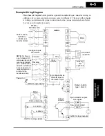
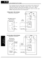
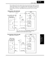
The two diagrams below show input wiring circuits using the inverter’s in24V
supply. Each diagram shows the connection for simple switches, or for a field device
with transistor outputs. Note that in the lower diagram, it is necessary to connect
terminal [L] only when using the field device with transistors. Be sure to use the correct
SR/SK switch position shown for each wiring diagram.
L200
2
L
24V
+
–
SK
SR
SK
SR
PCS
Input
circuits
1
5
Logic GND
1
5
GND
Open collector outputs,
NPN transistors
Input
switches
Sinking Inputs, Internal Supply
SR/SK switch = SK position
Field device
L200
2
L
24V
+
–
SK
SR
SK
SR
PCS
Input
circuits
1
5
Common,
to [PCS]
1
5
GND
PNP transistor
sourcing outputs
Input
switches
Sourcing Inputs, Internal Supply
SR/SK switch = SR position
Field device
to PNP bias
circuits
Logic GND
Summary of Contents for L200-002NFE2
Page 2: ......
Page 46: ......
Page 80: ......
Page 204: ......
Page 212: ......
Page 229: ...Glossary and Bibliography In This Appendix page Glossary 2 Bibliography 8 A ...
Page 280: ......
Page 297: ...L2002 Inverter Appendix D D 5 L1 L2 L3 PE L2002 inverter with book type filter M 3 ...

