L200
2
Inverter
Conf
igur
ing
Dr
iv
e P
a
ra
m
e
ters
3–63
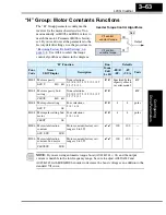
“H” Group: Motor Constants Functions
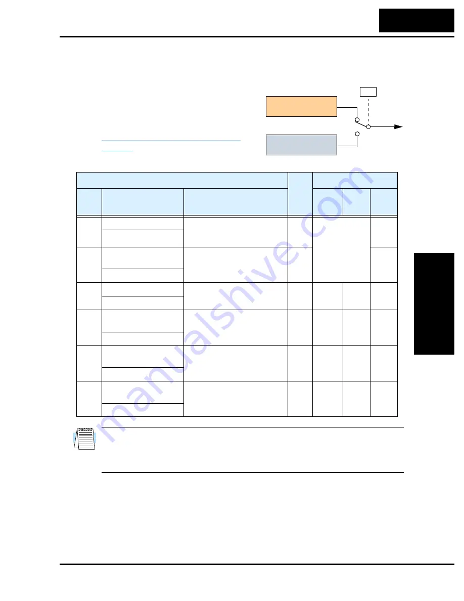
The “H” Group parameters configure the
inverter for the motor characteristics. You
must manually set H003 and H004 values to
match the motor. Parameter H006 is factory-
set. If you want to reset the parameters to the
factory default settings, use the procedure in
“Restoring Factory Default Settings” on
page 6–8
. Use A044 to select the torque
control algorithm as shown in the diagram.
NOTE:
If you are using automatic torque boost (A041/A241 = 01) and the output
current is unstable in the low frequency range, be sure to adjust A042/A242 and
A043/A243 with H006/H206 in order to decrease the boost voltage as an addition to the
standard V/f curve.
Output
A44
V/f control,
constant torque
V/f control,
variable torque
00
01
Inverter Torque Control Algorithms
“H” Function
Run
Mode
Edit
Lo Hi
Defaults
Func.
Code
Name /
SRW Display
Description
–FE(F)
(EU)
–FU
(USA)
Units
H003 Motor capacity
Nine selections:
0.2 / 0.4 / 0.75 / 1.5 / 2.2 / 3.7
5.5 / 7.5 / 11
✘ ✘
Specified by the
capacity of each
inverter model
kW
AUX K 0.4 kW
H203 Motor capacity, 2nd
setting
Nine selections:
0.2 / 0.4 / 0.75 / 1.5 / 2.2 / 3.7
5.5 / 7.5 / 11
✘ ✘
kW
2AUXK 0.4 kW
H004 Motor poles setting
Four selections:
2 / 4 / 6 / 8
✘ ✘
4
4
poles
AUX P 4p
H204 Motor poles setting, 2nd
motor
Four selections:
2 / 4 / 6 / 8
✘ ✘
4
4
poles
2AUXP 4p
H006 Motor stabilization
constant
Motor constant (factory set),
range is 0 to 255
✔ ✔
100
100
—
AUX KCD 100
H206 Motor stabilization
constant, 2nd motor
Motor constant (factory set),
range is 0 to 255
✔ ✔
100
100
—
2AUXKCD 100
Summary of Contents for L200-002NFE2
Page 2: ......
Page 46: ......
Page 80: ......
Page 204: ......
Page 212: ......
Page 229: ...Glossary and Bibliography In This Appendix page Glossary 2 Bibliography 8 A ...
Page 280: ......
Page 297: ...L2002 Inverter Appendix D D 5 L1 L2 L3 PE L2002 inverter with book type filter M 3 ...

