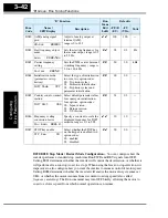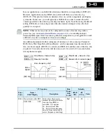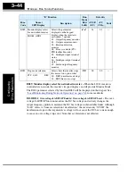
L200
2
Inverter
Conf
igur
ing
Dr
iv
e P
a
ra
m
e
ters
3–29
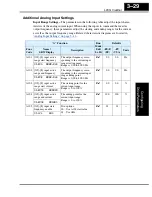
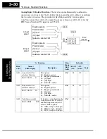
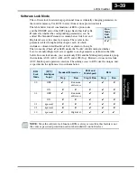
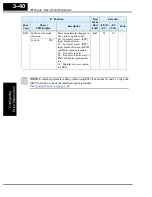
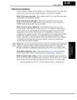
Additional Analog Input Settings
Input Range Settings –
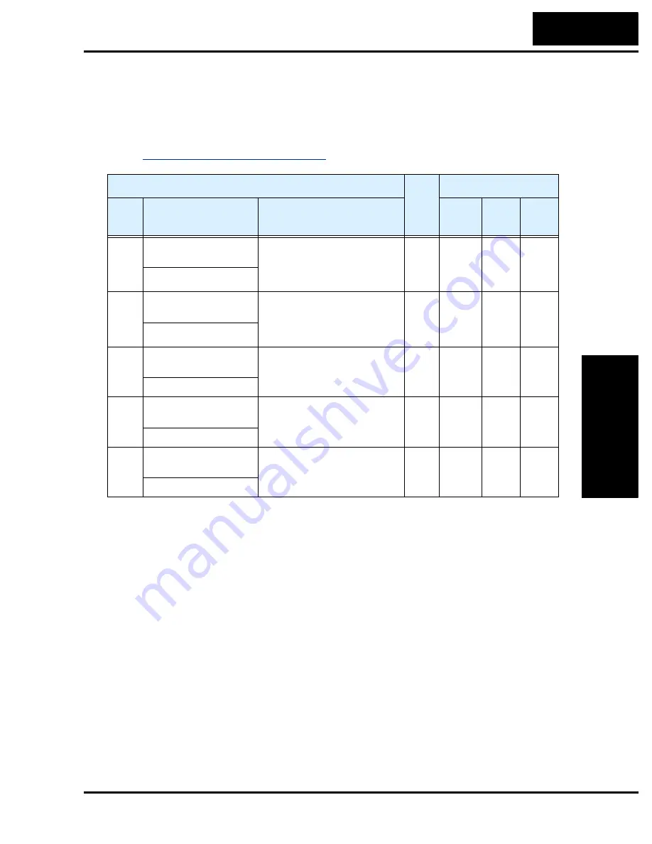
The parameters in the following table adjust the input charac-
teristics of the analog current input. When using the inputs to command the inverter
output frequency, these parameters adjust the starting and ending ranges for the current,
as well as the output frequency range. Related characteristic diagrams are located in
“Analog Input Settings” on page 3–14
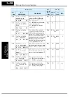
“A” Function
Run
Mode
Edit
Lo Hi
Defaults
Func.
Code
Name /
SRW Display
Description
–FE(F)
(EU)
–FU
(USA)
Units
A101 [OI]–[L] input active
range start frequency
The output frequency corre-
sponding to the current input
range starting point.
Range is 0.00 to 400.0 Hz
✘ ✔
0.0
0.0
Hz
OI-EXS 0000.0Hz
A102 [OI]–[L] input active
range end frequency
The output frequency corre-
sponding to the current input
range ending point.
Range is 0.00 to 400.0 Hz
✘ ✔
0.0
0.0
Hz
OI-EXE 0000.0Hz
A103 [OI]–[L] input active
range start current
The starting point for the
current input range.
Range is 0. to 100.%
✘ ✔
0.0
0.0
%
OI-EX%S 00000%
A104 [OI]–[L] input active
range end current
The ending point for the
current input range.
Range is 0. to 100.%
✘ ✔
100.
100.
%
OI-EX%E 00100%
A105 [OI]–[L] input start
frequency enable
Two options:
00 .. Use A101 start value
01 .. Use 0Hz
✘ ✔
01
01
—
OI-LVL 0Hz
Summary of Contents for L200-002NFE2
Page 2: ......
Page 46: ......
Page 80: ......
Page 204: ......
Page 212: ......
Page 229: ...Glossary and Bibliography In This Appendix page Glossary 2 Bibliography 8 A ...
Page 280: ......
Page 297: ...L2002 Inverter Appendix D D 5 L1 L2 L3 PE L2002 inverter with book type filter M 3 ...


