283
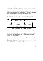
SCI3 operates as follows when receiving data.
SCI3 monitors the communication line, and when it detects a 0 start bit, performs internal
synchronization and begins reception. Reception is carried out in accordance with the relevant
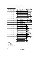
data transfer format in table 10.11. The received data is first placed in RSR in LSB-to-MSB order,
and then the parity bit and stop bit(s) are received. SCI3 then carries out the following checks.
•
Parity check
SCI3 checks that the number of 1 bits in the receive data conforms to the parity (odd or even)
set in bit PM in the serial mode register (SMR).
•
Stop bit check
SCI3 checks that the stop bit is 1. If two stop bits are used, only the first is checked.
•
Status check
SCI3 checks that bit RDRF is set to 0, indicating that the receive data can be transferred from
RSR to RDR.
If no receive error is found in the above checks, bit RDRF is set to 1, and the receive data is stored
in RDR. If bit RIE is set to 1 in SCR3, an RXI interrupt is requested. If the error checks identify a
receive error, bit OER, PER, or FER is set to 1 depending on the kind of error. Bit RDRF retains
its state prior to receiving the data. If bit RIE is set to 1 in SCR3, an ERI interrupt is requested.
Table 10.12 shows the conditions for detecting a receive error, and receive data processing.
Note:
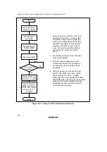
No further receive operations are possible while a receive error flag is set. Bits OER,
FER, PER, and RDRF must therefore be cleared to 0 before resuming reception.
Table 10.12 Receive Error Detection Conditions and Receive Data Processing
Receive Error Abbreviation Detection Conditions
Receive Data Processing
Overrun error
OER
When the next date receive
operation is completed while bit
RDRF is still set to 1 in SSR
Receive data is not transferred
from RSR to RDR
Framing error
FER
When the stop bit is 0
Receive data is transferred
from RSR to RDR
Parity error
PER
When the parity (odd or even) set
in SMR is different from that of
the received data
Receive data is transferred
from RSR to RDR


