212
3. Pin configuration
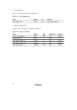
Table 9.11 shows the timer G pin configuration.
Table 9.11
Pin Configuration
Name
Abbrev.
I/O
Function
Input capture input
TMIG
Input
Input capture input pin
4. Register configuration
Table 9.12 shows the register configuration of timer G.
Table 9.12
Timer G Registers
Name
Abbrev.
R/W
Initial Value
Address
Timer control register G
TMG
R/W
H'00
H'FFBC
Timer counter G
TCG
—
H'00
—
Input capture register GF
ICRGF
R
H'00
H'FFBD
Input capture register GR
ICRGR
R
H'00
H'FFBE
Clock stop register 1
CKSTPR1
R/W
H'FF
H'FFFA

