A-2
Binary Access Table
Studio Color LCD Controller
channels corresponding to binary 1s and disable channels
corresponding to binary 0s. For more details, see the
next section.
Using Binary Preset Access
1.
Choose a preset number.
2.
Note the numbers listed in the group of 10 columns under the
heading “Analog Controller Channel Number”; this is the 10-
digit binary equivalent of the preset number you selected.
3.
Enable channels on your controller corresponding to binary
1’s and disable channels corresponding to binary 0’s. For
example, to use preset 1 enable channel 1 but do not enable
channels 2—10. To use preset 966, enable channels 2, 3, 7,
8, 9 and 10 but not channels 1, 4, 5 or 6.
0V = Disabled, 5V-10V = Enabled
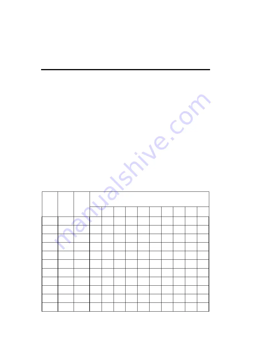
Table A-1. Presets, Preset Levels, and Analog Input Channels
Pre-
set
No.
Pre-
set
key
Pre-
set
level
Analog Controller Channel Number
1
2
3
4
5
6
7
8
9
10
Summary of Contents for High End LCD Controller for Studio Color
Page 9: ...viii Studio Color LCD Controller...
Page 16: ...xv Table of Tables Studio Color LCD Controller...
Page 34: ...1 12 Power Cord Cap Studio Color LCD Controller...
Page 114: ...4 30 Homing Fixtures Studio Color LCD Controller...
Page 130: ...5 16 Setting the Backlight Intensity Studio Color LCD Controller...
Page 162: ...6 32 Lightwave Control Center Studio Color LCD Controller...
Page 196: ...7 34 Crossloading Studio Color LCD Controller...


