


27
EN
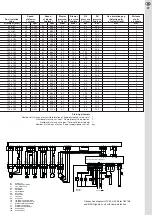
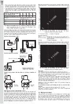
Start-up attempts
Number of start-ups at error: No formation of flame during the safety time"
1
Number of start-ups at error: "Flame blow-off in operation"
1
Number of start-ups at error: "Time-out blower speed"
1
Number of start-ups at error: "Power supply/power cut-off"
any
Speed
Speed
Blower
Blower
Oil
Oil
Re-circulation gap
Distance
Re-circulation
of blower,
of blower,
pressure,
pressure,
pressure
pressure
(Adjusting dial
of oil >
tube
1st level
2nd level
1st level
2nd level
1st level
2nd level
of actual width)
air nozzle
Ø [mm] x l [mm]
%
rpm
%
rpm
mbar
mbar
bar
bar
mm
mm
80 x 160
45
3.780
69
5.640
5,0
10,9
8,0
25,0
2
2
80 x 160
49
4.020
74
6.060
5,7
12,7
8,0
19,0
2
2
80 x 160
49
4.020
81
6.600
5,7
15,0
8,0
23,0
2
2
100 x 150
48
3.900
76
6.240
5,2
13,1
8,0
24,0
2
2
100 x 150
54
4.380
83
6.780
6,5
15,5
8,0
19,0
2
2
100 x 150
54
4.380
89
7.260
6,5
18,0
8,0
22,0
2
2
100 x 150
54
4.380
94
7.680
6,5
20,0
8,0
25,0
2
2
100 x 150
52
4.260
80
6.540
6,0
13,7
8,0
19,0
4
2
100 x 150
52
4.260
83
6.780
6,0
14,7
8,0
22,0
4
2
100 x 150
52
4.260
88
7.200
6,0
16,5
8,0
25,0
4
2
100 x 150
55
4.500
81
6.600
6,2
13,2
10,0
20,0
4
2
100 x 150
55
4.500
83
6.780
6,2
14,0
10,0
21,0
4
2
100 x 150
55
4.500
88
7.200
6,2
15,6
10,0
23,0
4
2
100 x 150
49
4.020
78
6.360
6,7
16,6
8,0
20,0
4
4
100 x 150
49
4.020
82
6.720
6,7
18,4
8,0
22,0
4
4
100 x 150
49
4.020
85
6.960
6,7
20,0
8,0
24,0
4
4
100 x 150
52
4.260
88
7.200
7,5
21,3
8,0
23,0
4
4
100 x 150
52
4.260
91
7.440
7,5
22,8
8,0
25,0
4
4
100 x 150
57
4.680
93
7.630
9,0
23,6
8,0
21,0
4
4
100 x 150
57
4.680
96
7.860
9,0
25,2
8,0
23,0
4
4
120 x 190
47
3.960
78
6.600
6,0
16,3
9,0
23,5
2
0
120 x 190
47
3.960
80
6.780
6,0
17,2
9,0
25,0
2
0
120 x 190
48
4.080
77
6.540
6,0
15,5
9,0
21,0
2
4
120 x 190
48
4.080
80
6.780
6,0
16,6
9,0
22,0
2
4
120 x 190
48
4.080
83
7.020
6,0
17,6
9,0
24,0
2
4
120 x 190
52
4.380
75
6.360
6,2
13,1
10,0
26,5
2
0
120 x 190
52
4.380
77
6.540
6,2
13,8
10,0
28,0
2
0
120 x 190
52
4.380
79
6.720
6,2
14,5
10,0
29,5
2
0
120 x 190
52
4.380
81
6.900
6,2
15,3
10,0
31,0
2
0
120 x 190
53
4.500
80
6.780
6,3
14,0
9,0
20,0
4
4
120 x 190
53
4.500
82
6.960
6,3
14,8
9,0
21,5
4
4
120 x 190
53
4.500
84
7.120
6,3
15,5
9,0
22,5
4
4
120 x 190
53
4.500
86
7.320
6,3
16,1
9,0
24,0
4
4
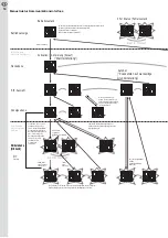
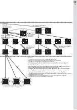
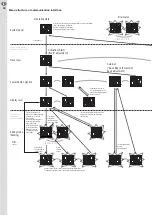
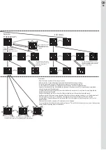
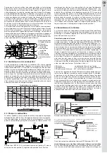
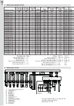
Connecting plan HLZ 45 with Elster CM 168
and ignition unit with flame recognition
V1
yellow/green
bl
ue
br
own
1
2
Elster CM 168
N
FL
N
L1
B1
L1
1
2
3
M
bl
ue
br
own
yellow/green
GM
1
2
3
4
5
black
green
yellow
B4 S3 T2 T1 N
L1
Y5
N
1/N, PE 230V 50Hz
L1
PE
N
Y5A
HS
F1
TB
L1
N
T1
T2
S3
B4
Connections
By customer
J
P
TR1
J
P
L1
T8 T7
B5
T6
2
3
T6
T7
T8
J
P
TR2
B5
Y4
Y4A
V2
yellow/green
bl
ue
br
own
1
2
1
2
3
N
bl
ue
br
own
yellow/green
PM
L1
Hall PWM GND
X6
X1
PE
1
4
X4
X9
X7
PE
PE
X8
Bus-
X5
Bus+
N
L1
Y1
PE
Bus-
Bus+
1
2
EE
1
2
H1
H2
h
P1
Y3
Y3A
Bus+ Bus- communication interface (CI)
Y2
yellow/green
4
3
2
1
br
own
bl
ue
black
OFV
N
DI
L1
X2
PE
NV1 NV2
L1
X13
PE
br
own
bl
ue
bl
ue
black
br
own
TT
1
3
2
1
2
B1
Oil firing unit
EE
External remote unlocking
F1
Fuse, maximum 10A
GM Blower
motor
H1 Signal
failure
H2 Signal
operation
HS Main
switch
OFV Oil
pre-heater
P1 Time
meter
PM Pump
motor
TB
Temperature or pressure limiter
TR
Temperature or pressure governor
TT
Ignition unit with flame monitoring
V1
Solenoid valve, first stage
V2
Solenoid valve, second stage
Y4A
Euro plug (4-pin)
Y5A
Euro plug (7-pin)
Connection diagram HLZ 45 with Elster CM 168
and BERU ignition unit with flame detection


