


For evaluation of the signal a circuit element, similar to the optical flame
detector, is integrated inside the ignition unit that displays the presence
of a flame through a high/low signal. As a result the ignition unit with flame
monitoring, as well as the optical flame detector, are usable with the same
burner control.
An LED in the housing of the ignition unit indicates the operating state of
the ionisation flame monitoring:
LED is OFF:
Ionisation flame monitoring is carrying no cur-
rent or faulty electrical connection.
LED is flashing:
Ionisation flame monitoring is active, no flame
has been detected.
LED is permanently ON:
Ionisation flame monitoring is active, flame
has been detected.
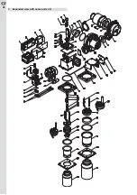
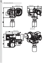
2.5 Ignition device
If an optical flame detector is used the ignition of the mixture occurs
through a separate ignition device (Danfoss EBI 4). An earth connection
is located in the primary connection socket to achieve a low electro-mag-
netic interference emission, i.e. the connection socket has three-pole
(phase, neutral wire and earth). Consequently the lateral earth lug, that is
used at the ignition unit with integrated flame monitoring is absent.
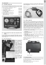
2.6 Oil firing unit with communication interface
For control and monitoring of the burner operation a digital oil firing unit
is used. This oil firing unit is approved in accordance with the currently
valid European Standard (EN 230:2005).
Adjusted to the requirements of the respective boiler the oil firing unit is
pre-parameterised by the factory. Possible user specific parameters are:
pre-purge time, pre-purge speed, post-purge time, post-purge speed,
safety time, safety time speed, stabilisation time, stabilisation time speed,
position of the starting point (first/second on-load stage), position of the
switching activating points for the solenoid valve V2, blower’s speed in
the first/second stage, setting range for the blower’s speed in the first/se-
cond stage, as well as the number of starting attempts at flame blow-off
(during the safety time and while in operation).
The start of the burner occurs dependent of the factory’s pre-adjustments
in the first or second stage. Depending on the conditions at the place of
installation of the system the initial operation of the burner by the profes-
sional workmen requires only a fine-tuning of the blower. The necessary
alteration of the pre-adjusted blower speed for the first/second stage oc-
curs through a separately arranged communication interface (CI). Beyond
this, the communication interface (CI) also serves to describe the burner’s
operating condition, issue of the error code, and for unlocking during ab-
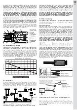
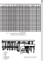
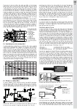
High voltage
Blue,
N
Blue,
N
PE,
Earthing
Brown,
voltage
supply, L1
Black,
opto-coupler,
FL
LED
Brown,
Ignition
"ON": 230 V AC
"OFF": 0 V
Blue, N
Brown,
voltage supply, L1
Ignition
"ON": 230 V AC
"OFF": 0 V
PE, Earthing
50/60 Hz
20 kHz
normal occurrences. A rotary encoder and a button are visible at the com-
munication interface to call up the respective menu and to alter the pre-
adjusted values.
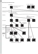
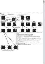
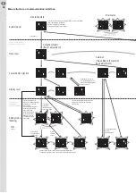
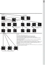
The corresponding menu structure is shown in image page 34, 35.
The burner is normally put into operation to adjust the blower speed
(warm adjustment). Alternatively it is also possible to change the blower
speed while the burner is turned off (cold adjustment). However, this ac-
tion only becomes necessary if the burner cannot be put into operation
with the factory preset parameters due to extreme local conditions in re-
lation to the exhaust gas system, the outdoor temperature, or the height
of the place of installation. If an unintended change has been made within
the course of the adjustment work a re-setting of the factory preset
parameters on-site is possible (Auto Set). Further more factory preset
para meters can be changed by inserting a “Burner Chip Card” (BCC).
Assuming that the adaptations of the blower speed of the first and second
stage have been taken the blower speed during the safety/stabilisation
time, as well as the position of the starting points of the solenoid valve for
the second stage, are newly calculated.
Display of operating state for communication interface CI 1
State of operation
1st or 2nd on-load stage
0 Standby
1 Pre-heating phase
2 Control of working contacts
3 Pre-purge
4 Wait for ignition speed
5 Pre-ignition
6 Safety time (release of fuel)
7 Flame stabilisation time
8 Release of governor (change-over of 1st/2nd stage is possible)
9 Wait for post-purge
10 Post-purge
Error codes of communication interface CI 1
The last 10 errors that appeared may be retrieved via the subse-
quently following error codes.
3 Time-out of blower speed
4 No formation of flame during the safety time
5 Flame blow-off during the burner’s operation
10 Error remote unlocking (more than 5 activations of remote unlocking
within 15 minutes)
11 Formation of flame during pre-purge/pre-ignition
15 Time-out of oil pre-heater
32 Voltage supply (under-voltage, voltage cut-off)
48 Interruption of bus communication
The burner must be disconnected from the power supply system to delete
display of the error code “10”.
The starting sequence of the burner begins as soon as a request
signal for heat is initiated from the boiler control system. The oil
pre-heater is first started. As soon as the oil pre-heater has achie-
ved the required temperature and the thermal switch is closed, the
blower is started and all operating contacts are tested. After com-
pletion of the test and after expiration of pre-purge the ignition
speed is started up. After the ignition speed is archived the pump
motor in turned on. After the pre-ignition time the solenoid valve
V1 (start in the first stage) or both solenoid valves (V1 and V2 star-
ting in the second stage) will be opened. If a flame is built within
the safety time the burner will still run for a short period in the pre-
selected start-up stage to stabilise the flame. The blower’s speed
may be varied compared with the ignition speed during the stabi-
lisation time. After the stabilisation time has expired the burner is
operated in that stage, which is set by the boiler control. If the re-
quest signals for heat are eliminated the solenoid valves will be
closed, the pump motor cut off, and the blower will be run for a
pre-set time with the post-purge speed.
To achieve the smoothest possible and low emission change of the load
stages, the on/off-duty of the solenoid valve for the second stage occurs
dependent on the blower’s speed. The switching points that have been
parameterised by the factory are newly calculated at each adjustment of
the blower’s speed so that the position of the switching points remains
relatively unchanged to the blower’s speed at the first and second load
stage.
22
EN