26
EN
5.
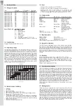
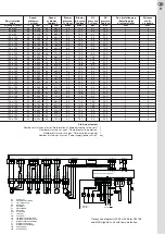
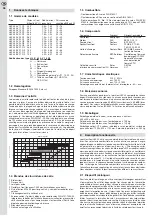
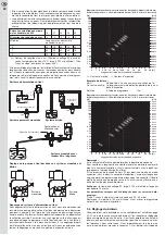
Basic adjustment table
6
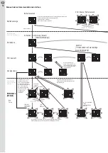
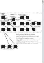
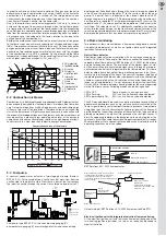
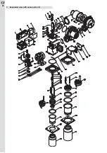
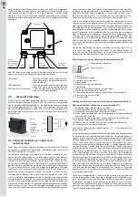
Wiring diagram
Revolutions per minute
HRG 134
RG 148
Maximum rpm, n
max
8220 rpm
8520 rpm
Pre-purge speed n
prp
75%
60%
Offset ignition speed rpm o
i
by -3%
by -8%
Offset flame stabilisation speed rpm o
fs
by -2%
by -4%
Post-purge speed n
pop
75%
75%
Turn-on speed V2 n
on,V2
60%
68%
Turn-off speed V2 n
off,V2
60%
75%
Factory Parameter
Times
Time of pre-purge, t
prp
5 sec.
Pre-ignition time, t
pri
10 sec.
Safety time, t
S
5 sec.
Flame stabilisation time, t
fs
15 sec.
Post-ignition time, t
poi
3 sec.
Post-purge time, t
pop
120 sec.
Firing
Firing
Start
Oil mass
Oil mass
output
output
1st/2nd
flow
flow
Burner model
1st level
2nd level
level
Blower
Oil nozzle
1st level
2nd level
Air nozzle
Burner tube
kW
kW
USgal/h 80° H
kg/h
kg/h
Ø mm
Ø mm
HLZ 45 AV 17 G1
10
18
2
HRG 134
0,30
0,84
1,52
17,50
80
HLZ 45 AV 17 G1
13
20
2
HRG 134
0,35
1,10
1,69
17,50
80
HLZ 45 AV 17 G1
13
22
2
HRG 134
0,35
1,10
1,85
17,50
80
HLZ 45 AV 19 G1
14
24
1
HRG 134
0,40
1,18
2,02
19,00
80
HLZ 45 AV 19 G1
16
26
1
HRG 134
0,45
1,35
2,19
19,00
80
HLZ 45 AV 19 G1
16
28
1
HRG 134
0,45
1,35
2,36
19,00
80
HLZ 45 AV 19 G1
16
30
1
HRG 134
0,45
1,35
2,53
19,00
80
HLZ 45 AV 22 G1
20
32
1
HRG 134
0,55
1,69
2,70
22,00
80
HLZ 45 AV 22 G1
20
34
1
HRG 134
0,55
1,69
2,87
22,00
80
HLZ 45 AV 22 G1
20
36
1
HRG 134
0,55
1,69
3,04
22,00
80
HLZ 45 AV 24 G1
26
38
1
HRG 134
0,60
2,19
3,20
24,00
80
HLZ 45 AV 24 G1
26
40
1
HRG 134
0,60
2,19
3,37
24,00
80
HLZ 45 AV 24 G1
26
42
1
HRG 134
0,60
2,19
3,54
24,00
80
HLZ 45 AV 24 G2
27
44
1
RG 148
0,65
2,28
3,71
24,00
80
HLZ 45 AV 24 G2
27
46
1
RG 148
0,65
2,28
3,88
24,00
80
HLZ 45 AV 24 G2
27
48
1
RG 148
0,65
2,28
4,05
24,00
80
HLZ 45 AV 24 G2
29
50
1
RG 148
0,75
2,45
4,22
24,00
80
HLZ 45 AV 24 G2
29
52
1
RG 148
0,75
2,45
4,38
24,00
80
HLZ 45 AV 24 G2
33
54
1
RG 148
0,85
2,78
4,55
24,00
80
HLZ 45 AV 24 G2
33
56
1
RG 148
0,85
2,78
4,72
24,00
80
HLZ 45 BV 27 G2
35
58
1
RG 148
0,85
2,95
4,89
27,00
100
HLZ 45 BV 27 G2
35
60
1
RG 148
0,85
2,95
5,06
27,00
100
HLZ 45 BV 27 G2
39
62
1
RG 148
1,00
3,29
5,23
27,00
100
HLZ 45 BV 27 G2
39
64
1
RG 148
1,00
3,29
5,40
27,00
100
HLZ 45 BV 27 G2
39
66
1
RG 148
1,00
3,29
5,56
27,00
100
HLZ 45 BV 31 G2
48
68
1
RG 148
1,10
4,05
5,73
31,00
100
HLZ 45 BV 31 G2
48
70
1
RG 148
1,10
4,05
5,90
31,00
100
HLZ 45 BV 31 G2
48
72
1
RG 148
1,10
4,05
6,07
31,00
100
HLZ 45 BV 31 G2
48
74
1
RG 148
1,10
4,05
6,24
31,00
100
HLZ 45 BV 31 G2
50
76
1
RG 148
1,25
4,22
6,41
31,00
100
HLZ 45 BV 31 G2
50
78
1
RG 148
1,25
4,22
6,58
31,00
100
HLZ 45 BV 31 G2
50
80
1
RG 148
1,25
4,22
6,75
31,00
100
HLZ 45 BV 31 G2
50
82
1
RG 148
1,25
4,22
6,91
31,00
100
Connecting plan HLZ 45 with Elster CM 168
V1
yellow/green
bl
au
b
rown
b
rown
bl
ue
bl
ue
black
1
2
Elster CM 168
N
FL
N
L1
B1
Oil firing unit
EE
External remote unlocking
F1
Fuse, maximum 10A
GM Blower
motor
H1 Signal
failure
H2 Signal
operation
HS Main
switch
LD Flame
detector
OFV Oil
pre-heater
P1 Time
meter
PM Pump
motor
TB
Temperature or pressure limiter
TR
Temperature or pressure governor
TT Ignition
unit
V1
Solenoid valve, first stage
V2
Solenoid valve, second stage
Y4A
Euro plug (4-pin)
Y5A
Euro plug (7-pin)
B1
L1
LD
b
rown
TT
1
2
3
M
bl
ue
b
rown
yellow/green
GM
1
2
3
4
5
black
green
yellow
B4 S3 T2 T1 N
L1
Y5
N
1/N, PE 230V 50Hz
L1
PE
N
Y5A
HS
F1
TB
L1
N
T1
T2
S3
B4
Connections
By customer
J
P
TR1
J
P
L1
T8 T7
B5
T6
2
3
T6
T7
T8
J
P
TR2
B5
Y4
Y4A
V2
yellow/green
bl
ue
b
rown
1
2
1
2
3
N
bl
ue
b
rown
yellow/green
PM
L1
Hall PWM GND
X6
X1
PE
1
4
X4
X9
X7
PE
PE
X8
Bus-
X5
Bus+
N
L1
Y1
PE
Bus-
Bus+
1
2
EE
1
2
H1
H2
h
P1
Y3
Y3A
Bus+ Bus- communication interface (CI)
Y2
yellow/green
4
3
2
1
b
rown
bl
ue
black
OFV
N
DI
L1
X2
PE
NV1 NV2
L1
X13
PE
Connection diagram HLZ 45 with Elster CM 168
and optical flame monitor
BST solutions KLC 2002


