21
EN
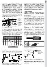
In order to achieve an intensive recirculation of flue gas over the entire
performance range in combination with a high stability of the flame the
combustion air is supplied in a swirled jet. The image below shows
schematically the mode of operation of the mixing device. The combus-
tion air enters through a nozzle into the flame tube.
Due to the rapid cross-sectional enlargement of the air jet a vacuum
accrues at the edge of the air nozzle through which the hot flame gases
are transported from the inside of the flame conduit into the evaporating
zone. Besides this, cooled flue gases reach through openings of the flame
tube from the combustion chamber into the evaporating zone. In addition,
a backward zone is developed in the flame’s rotation centre due to the
swirled flow of the combustion air.
Besides the avoidance of soot formation the intensive return of flue gases
to the flame’s root also achieves a reduction of nitrogen oxide emissions
(NOx). Two mechanisms essentially help this occur. On the one hand the
oxygen partial pressure of the mixture is reduced. Therefore the local con-
centration of dissociated oxygen molecules that react with the nitrogen
of the combustion air to NOx is reduced. On the other hand the flame
temperature is reduced through the recirculating flow of inert flue gases
with a higher specific heat capacity (CO
2
and H
²
O).
A Swirl generator
B Ignition electrode
C Air nozzle
D External re-
circulation zone
E Internal re-
circulation zone
F Flame
G Flame tube
H Injection nozzle
I Oil preheater
K Air
2.2 Combustion air blower
Combustion air is delivered through a speed regulated EC blower that has
been especially designed for the requirements of modern blue flame bur-
ners. It mainly distinguishes itself by high pressures and an extremely high
stiffness of pressure at low revolutions. Therefore it allows a pulsation-free
start of the burner even at high furnace back-pressure. In connection with
the especially developed silencer at the blower’s entry the smoothness of
running ensures a pleasantly low operating noise level of the burner. In
comparison with conventional blower solutions the high degree of effecti-
veness results in a clear reduction in electric energy consumption.
2.3 Fuel pump
A constant speed motor actuates a two-stage gear pump (Danfoss,
BFP 52 E L3). This pump delivers a continuous fuel mass flow from the
suction side to the pressure side. From there, a part of the fuel reaches
the injection nozzle through the current-less closed solenoid valve V1.
H
I
G
C
K
A
D
E
B
F
Characteristic curves of the blowers
0
5
10
15
20
25
30
35
40
0
20
40
60
80
100
120
140
160
180
20
Air volume flow in m
3
/h
Pressure in mbar
ebm-papst HRG 134
ebm-papst RG 148
Another partial flows back again through the current-less open solenoid
valve V2 and the pressure regulator P1 to the suction side of the gear
pump. This partial flow is redirected at the closed solenoid valve V2
through the pressure regulator P2. Depending on the valve’s position eit-
her the pressure regulator P1 or the pressure regulator P2 is active. The
solenoid valve V1 is under current for the operation of the burner in the
first stage. The solenoid valve V2 is additionally supplied with current to
switch into the second stage. In order to achieve a correct function of this
switching the adjusted pressure at the pressure regulator P2 must always
be beyond the pressure that has been set at pressure regulator P1.
2.4 Flame monitoring
Two optional systems are available as a flame-monitoring device, namely
an optical flame detector, as well as an ignition device with integrated
ionisation flame monitoring.
Optical flame detector
Real flames release luminous radiation with an unsteady changing fre-
quency. This kind of “flickering“ of the flame is used for the especially de-
veloped optical flame detector (BST Solutions KLC 2002) for blue flame
burners to recognise flames. The evaluation of the optical signal, as well
as the conversation into an evaluated signal, occurs through a micro pro-
cessor based control that is integrated into the flame detector. This flame
detector differs from other optical flame monitoring devices in that it eva-
luates only the flickering of the flame. The constant luminous radiation of
the glowing recirculation tube or other components inside the combustion
chamber is completely cut out. A radiation with constant frequency also
leads to no flame detection. It is not necessary to adjust the sensitivity.
Only an LED in the flame detectors housing indicates the current operating
state of the flame sensor. Following modes can be distinguished:
LED is OFF:
Flame monitor is carrying no current
LED is flashing:
KLC is active, no flame has been detected
LED is permanently ON:
KLC is active, flame has been detected
The LED may additionally be used as an optical interface to read different
performance parameters (such as e.g. pulse counter, visualisation of the
flame’s signal intensity, serial number). In order to prevent, at very extreme
energy densities, that the characteristic flickering signals of the flame will
be interferred by the emitting radiation of the recirculation tube and other
glowing components, an optical filter precedes the real light sensor. It
dims the appearing radiation in the background in a partial region of the
spectrum so that the usable flame signal appears comparatively stronger.
Misinterpretations that under extreme conditions can also lead to unsafe
operating conditions are also avoided.
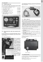
BST Solutions KLC 2002 flame detector.
Output wiring of BST Solutions KLC 2002 flame monitor/Beru ZTÜ.
Electrical ignition unit with integrated ionisation flame monitoring
At the electrical ignition unit with ionisation flame monitoring one of the
two existing ignition electrodes is used as an ionisation electrode to
monitor the flame.
Accumulation of cables
Blue
Black
Brown
LED
Black, opto-coupler, FL
Brown, power supply, L1
Blue, N
Brown, power supply, L1
Black, opto-coupler, FL
“Digital signal“
When applying the voltage:
- Flame OFF, no potential, “high“
- Flame ON, “low“
With the alternating voltage at FL the signal is
rectified through the transistor, and the diode
is connected in series as well (to enable a
connection to the burner control unit with ionisation
flame monitoring).
Blue, N
Signal
Electronic strobe
Flame sensor
Series resistor to protect the transistor
Electronic control
at the flame
sensor
Fuel pump, type BFP 52 E L3, injection pressure gauging (P),
prime pressure gauging (V), pressure regulator first and second stage.
Pressure side
Suction side
Return side
V1
V2


