25
EN
necessary to carry out the measuring of the CO
2
content, as well as
determining the soot number. We would therefore recommend for both
on-load stages to run the burner with a CO
2
content within the range
12.5%-13.0%. Make sure not to exceed the soot number of Rz = 0.5 when
operating the burner.
Adjustment of the combustion airflow
Adjustment of the combus-
tion air occurs through the
communication interface. In
case of a warm adjustment
(menu = Activation “A“), i.e.
the setting of the blower
speed while the burner is
running, a request signal of
heat for the first stage must
be on the communication in-
terface. An additional re-
quest signal of heat for the
second stage is also permit-
ted but rather unnecessary for the adjustment process. When dialling the
blower speed for the second stage this will be automatically started even
without the corresponding request signal of heat. If the burner cannot run
with the pre-adjustment made by the factory, or with a mistakenly altered
parameter set, alternatively also a cold setting (menu = Parameter “P“)
can be undertaken, i.e. an adjustment of the blower speed while the bur-
ner is not running. In order to avoid starting up the burner unintentionally
during the adjustment work the communication interface will ignore a pos-
sibly existing request signal of heat. It is also possible to call up the Au-
toSet function for faulty entries in the menu – Activation “A“ – in order to
call up again the initially pre-adjusted blower speed by the factory. More
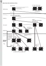
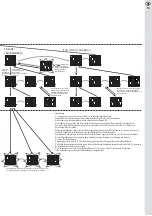
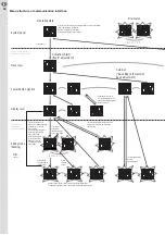
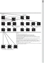
details as to the menu mode are available in image page 34, 35.
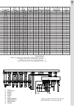
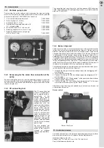
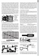
A pressure nipple is provided at the cover of the blast connection to mea-
sure the blower’s pressure. Reference values for the adjustment values of
the blower’s pressure, as well as the resulting blower pressure, may be
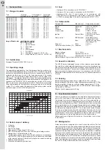
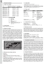
taken from basic adjustment table on page 26, 27.
Adjustment of the oil mass flow
The injected oil mass flow
arises from the size of the
nozzle and the injection
pressure set at the pressure
regulator of the oil pump for
the respective load stage.
Reference values for the size
of the nozzle and oil pressure
may be taken from basic ad-
justment table. A pressure
measuring connecting piece
is provided at the pump to
measure the oil pressure.
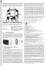
Adjustment of the recirculation of flue gas
By twisting the adjustment screw clockwise the recirculation gap will be
decreased and therefore the recirculated flue gas flow reduced, while the
NOx content is slightly increased. Conversely, an increase of the recircu-
lation gap by twisting the adjustment screw counter-clockwise would lead
to an intensifying of the flue gas recirculation, thereby causing a reduction
of the NOx content of the flue gas. An increasing rate of recirculation
would reduce the stability of the flame. Such reaction would impose tight
limits to the recirculation of flue gas as a measure to reduce the NOx con-
tent. If the recirculation gap is opened too wide the flame blows off,
particularly during the start up of the burner. This is attributed to the fact
that the combustion chamber contains air but not flue gases, similar to if
the burner is running. This would mean that air is recirculated wherefore
the mixing becomes lean in oil and less ignitable. Additionally, the air ac-
cess would also have a negative effect on the stabilising mechanisms of
the flame. In regard to these facts we would therefore recommend ob -
serving the measures for the recirculation gap as stated in the basic
adjustament table. In this connection you should also consider that the
minimum gap width is limited to 2 mm by a mechanical stop.
To achieve better flame stability starting the burner with a cooled-down
combustion chamber would represent the worst case. In order to ensure
that a start under these circumstances is possible the water content of
the boiler as well as the recirculation tube should be cooled down as far
as possible before a starting attempt is undertaken. If a start has not been
effected, or in the event of a pulsating start, you should decrease the re-
circulation opening.
4.
Maintenance of the burner
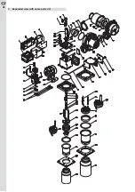
When maintenance is required, loosen the clamping screw at the flange
by means of the hexagon key), turn the burner to the left side and pull it
out of the burner pipe. Subsequently, you should hang up the burner over
the service holder that is arranged above the housing at the clamping
screw of the flange. An ideal access to all components in the range of
the mixing unit is ensured in this so-called service position.
Attention: The mixing head and ignition electrodes may be very hot!
Exchange of nozzle
• Loosen the hexagon fastening screw for the mixing head by 4 mm and
remove the mixing head.
• Choose a suitable oil nozzle according to basic adjustment table.
• Unscrew the existing oil nozzle and replace it with a new one.
• Adjust the distance between the air and oil nozzle according to the
basic adjustment table. Subsequently, check the distance by means of
the adjustement gauge and make re-adjustments. If the distance of oil
and air nozzles is correct fasten the mixing head by the fastening screw
at the adjusted position.
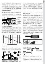
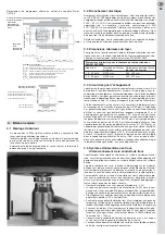
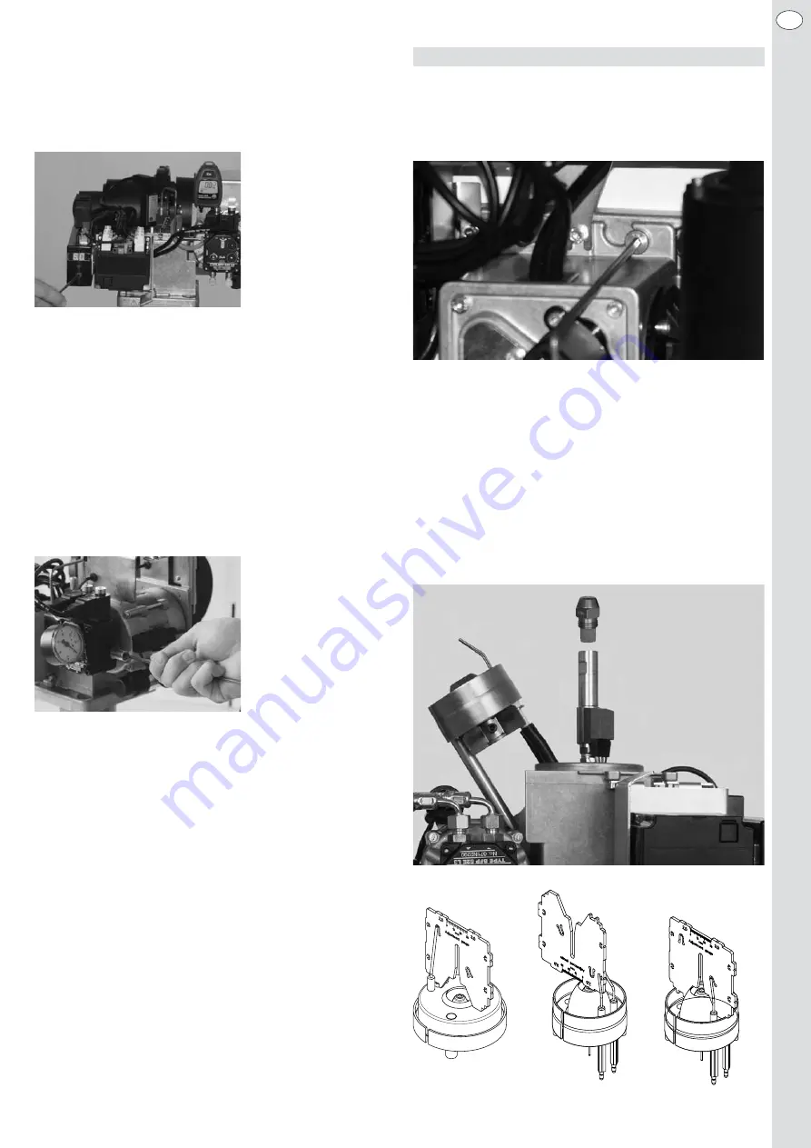
• To ensure safe ignition you should check the position of the ignition
electrodes by means of the adjustment template and re-adjust, if ne-
cessary (see image below).


