30
4.
Maintenance of the burner
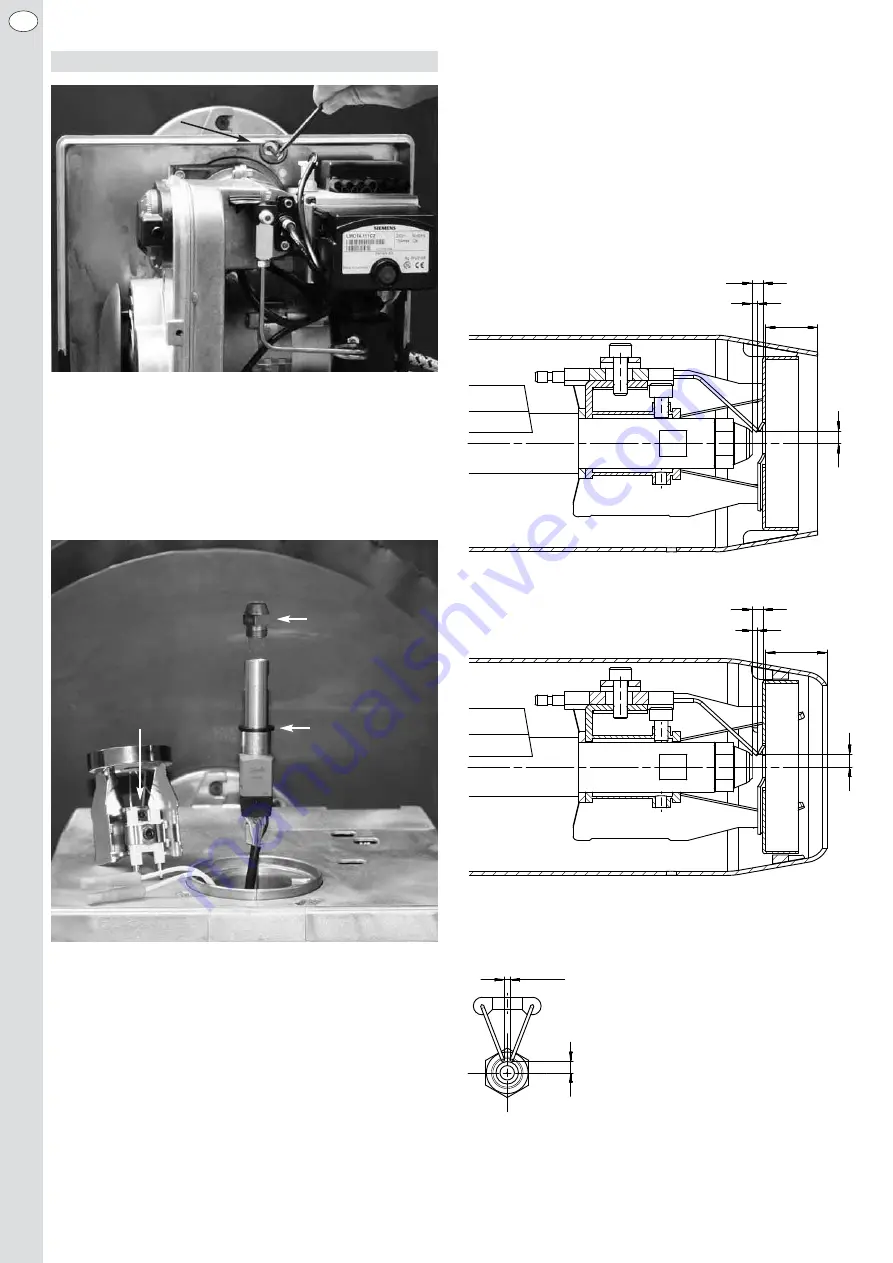
When maintenance is required, loosen the clamping screw at the flange
by means of the hexagon key by 4mm, turn the burner to the left and pull
it out from the burner pipe. Subsequently, you should fit the burner to the
service screw of the flange using the lug in the base plate (version with
cover hood) or the lug at the burner housing (version without cover hood).
Easy access to all components around the mixing unit is ensured in this
so-called service position.
Attention:
Baffle plate and ignition electrodes may be very hot. Risk of injury!
Service position
Replacement of nozzle and diaphragm valve
– Loosen the mounting screw for the baffle plate by 4mm using a hexagon
socket wrench and remove the baffle plate.
– Select an appropriate oil nozzle according to the basic adjustment table
(see chapter 5).
– Unscrew the existing oil nozzle.
– Inspect the used nozzle for burners with mixing unit E and F: If there
are traces of major thermal load (coke deposits on the outer coating,
rubber-like coke products on the nozzle filter), we recommend the
replacement of the diaphragm valve as well. To this end, remove the
diaphragm valve from the oil pre-heater using a M5 screw and insert a
new diaphragm valve (order no. 10021.00003). For the easy replace-
ment of the diaphragm valve, a knurled-head screw (order no.
10023.00026) is available as accessory.
– Screw in new oil nozzle.
– Mount the baffle plate to the oil pre-heater and adjust the distance
between baffle plate and oil nozzle according to the dimensional draw-
ing. A distance washer is mounted onto the oil pre-heater in the
factory, resulting in correct adjustment due to the limit stop. Alterna-
tively, the distance between baffle plate and oil nozzle can be adjusted
by inserting the supplied hexagon socket screw (wrench size 4mm)
between the baffle plate and the oil nozzle. Then locate the baffle plate
at the set position using the mounting screw.
– To ensure the reliable ignition of the mixture, the adjusting dimensions
of the ignition electrodes must be checked and readjusted according
to the dimensional drawing, if necessary.
Adjusting dimensions of mixing unit and ignition electrode
EN
4 mm
2 mm
15 – 35 mm
5 mm
4 mm
2 mm
17 – 37 mm
5 mm
2 – 3 mm
5 mm
A /B
A /B / E / F
E / F
Service screw
Oil nozzle
Mixing head
mounting screw
Distance washer
Summary of Contents for HL 60 ALV.2
Page 15: ...15 DE 7 Explosionszeichnung mit Ersatzteilliste...
Page 20: ...20 DE 9 Brennerabmessungen HL 60 ALV 2 BLV 2 Schiebeflansch HL 60 ALV 2 BLV 2 Unitflansch...
Page 33: ...33 EN 7 Expanded view with spare parts list...
Page 38: ...38 EN 9 Burner dimensions HL 60 ALV 2 BLV 2 sliding flange HL 60 ALV 2 BLV 2 unit flange...
Page 51: ...51 FR 7 Vue clat e avec liste des pi ces de rechange...
Page 69: ...69 IT 7 Disegno esploso con elenco parti di ricambio...


