background image

27

The burner must be connected in accordance with DIN 4791:1985-09
using a 7-pole Euro plug. Wiring details are provided in the wiring diagram
in chapter 6. The factory will deliver the burner together with the Euro
 connector (female plug). The Euro connector male plug is not included in
the scope of delivery. For burners with cover hood, the cables are inserted
through a rubber grommet in the base plate, where the oil tubes are
 inserted as well.

3.3 Combustion chamber - minimum dimensions

In order to ensure reliable operation and low pollutant emissions, the
 geometry of the combustion chamber must meet the test flame tube
 standards according to DIN EN 267:2011-11.

3.4 Exhaust gas system

The burner is designed for operation dependent on ambient air as well as
for operation independent of ambient air. For operation dependent on am-
bient air we recommend the installation of a draft limiter into the flue gas
system in order to ensure constant pressure in the combustion chamber.
The low pressure in the combustion chamber which can be adjusted on
the draft limiter should be –0.1mbar compared to the ambient pressure.
The flue draft to be adjusted for overpressure boilers is provided in the
boiler manual.

For operation independent of ambient air, the burner can be connected
to the air exhaust separator of an air exhaust system using optional air in-
take connection pieces (Ø 50mm and Ø 80mm). For operation indepen-
dent of ambient air, no draft limiter may be installed into the exhaust pipe.
Furthermore, you must ensure that the heating boiler used is suitable for
the selected exhaust gas system with regard to exhaust gas composition
and exhaust gas temperatures. 
The relevant applicable local provisions regarding the exhaust gas system
must also be taken into consideration.

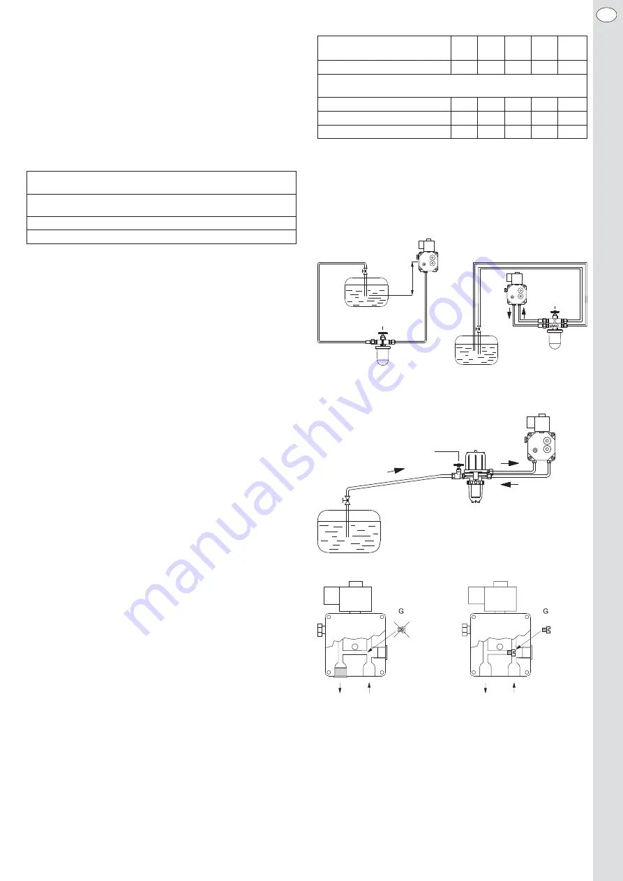
3.5 Oil supply system, oil pipe dimensions

The burner can optionally be operated as a pure one-line system, a one-
line system with filter-aspirator combination (the pump is operated simi-
larly to a two-line system), or a two-line system. 
The burner is preset for a two-line system as a standard. When converting
the pump to one-line operation, make sure to seal the return piece with a
sealing plug and remove the shift screw in the junction canal between the
pressure and intake side. 
In order to avoid any malfunction of the burner caused by the oil supply
system, we recommend operating the burner in a pure one-line system
with filter-aspirator combination. The following points should be con -
sidered:
•  Maximum intake height without booster pump: 3.5m
•  Up to a nominal thermal output of the boiler of 50kW, we recommend

an oil pipe with an internal diameter of 4mm for the one-line system
with filter-aspirator combination.

•  The pipes should be arranged such that the boiler together with the bur-

ner can be swiveled out by 90°.

•  Upstream of the flexible oil pipes, you must install a valve at the end of

the rigid oil pipe (already integrated in commercial filter-aspirator com-
binations).

•  A filter-aspirator combination must be installed upstream of the burner.

Insert of sintered plastic 20-75 μm for boiler capacities of up to 40 kW,
for boiler capacities >40 kW sieve with 100-150 μm of fineness.

•  The highest point of the oil pipe should not exceed 3.5m above the end

of the intake pipe of the tank.

•  The pipes must be installed in such a manner that no liquid may be

 allowed to escape (raise) from the container.

•  If the highest level of the fuel in the oil tank is above the oil pump of the

burner, you must install an anti-lifter valve at the highest point of the oil
pipe and as close as possible to the oil tank.

•  The oil pipe and the connection to the burner must meet the current

provisions. It is absolutely imperative that you check the existing oil
supply as from the time of oil tapping from the oil tank.

Combustion chamber minimum dimensions according to 
DIN EN 267:2011-11

Oil flow

Diameter or

Depth from the

height and width

baffle plate

1.0 - 2.0 kg/h

Ø 225 mm

250 - 350 mm

2.0 - 6.0 kg/h

Ø 300 mm

350 - 612 mm

*  H = max. intake height in m (low sulphur fuel oil EL, oil temperature 

>10 °C, up to 700 m above sea level, 1 filter, 1 check valve, 6x 90 °
bends).

For other system requirements (intake height, pipe lengths and nominal
thermal output of the boiler), you should consider the following diagrams
for pipe dimensioning.

Oil supply system

One-line system                  Pure two-line system

One-line system with filter-de-aerator combination

Setting at the fuel pump for one-line and two-line system

Absperreinrichtung

Filter-Entlüfter - 

Kombination

Einstrang-
system

Zweistrang-
system

Absperreinrichtung

Filter

Absperr-
einrichtung

Filter

H

max

 =

3,5 m

EN

Nominal thermal output of the
boiler in kW

16

20

25

35

50

Internal pipe Ø in mm

4

4

4

4

4

H* in m

max. zulässige 
Leitungslänge in m:

0

30

30

30

30

20

1

30

30

30

23

15

2

30

28

23

16

10

Valve system

Valve system

Valve system

One-line
system

Two-line
system

Filter-de-aerator
combination

Summary of Contents for HL 60 ALV.2

Page 1: ...kW Technische Information Montage und Betriebsanleitung Technical information Assembly and operating instructions Caract ristiques techniques Instructions de montage et de service Informazioni tecnic...

Page 2: ...r nahezu alle Schraub verbindungen ein rascher Austausch jeglicher Komponente m g lich Mit einem Brenner von Herrmann hat Heizen mit l Tradition und Zukunft Auch k nftig wird l als Brennstoff eine wi...

Page 3: ...weizer Luftreinhalteverordnung LRV Swiss Ordinance on Air Pollution Control The extremely compression rigid blower which was specially designed for the combustion of fuel oil ensures the pulsation fre...

Page 4: ...r la protection de l air OPair Extr mement r sistant la pression et sp cialement con u pour la combustion du fioul le ventilateur garantit un d marrage du br leur sans pulsation Gr ce d autres composa...

Page 5: ...o l inquinamento atmosferi co OIAt Il ventilatore estremamente resistente alla pressione concepito appo sitamente per la combustione di gasolio garantisce l avvio del brucia tore senza pulsazioni Altr...

Page 6: ...ponente Hersteller Modellbezeichnung Motor Hanning O1A095 030 lpumpe Danfoss BFP 21 L3 Danfoss BFP 21 L3 LE lvorw rmer Danfoss FPHB 5 Danfoss FPHB LE Z ndeinheit Danfoss EBI 4 Fotowiderstand Danfoss L...

Page 7: ...schlusssystem der Firma Danfoss LE System ausger stet Hierzu wird im l vorw rmer ein federbelastetes Membranventil eingebaut Dieses ffnet bei einem ldruck von ca 5 bar und schlie t durch die Federkraf...

Page 8: ...tzlich die Ausg nge f r die Brenn stoffventile den Brennermotor und die Z ndeinrichtung sofort 1s ab geschaltet Nach St rabschaltung bleibt der Feuerungsautomat verriegelt die St rsignalleuchte leuch...

Page 9: ...werden Um St rungen des Brenners durch das lversorgungssystem zu vermei den empfehlen wir den Brenner in einem Einstrangsystem mit Filter Entl fter Kombination zu betreiben Folgende Punkte sind dabei...

Page 10: ...t rt werden Ist eine vollst ndige Entl ftung der lversorgung bis dahin nicht erfolgt empfeh len wir f r die Entl ftung eine externe Saugpumpe einzusetzen 3 6 lanschluss an Brenner Die an der Pumpe mon...

Page 11: ...er Stellschraube f r die Luftdrossel entgegen dem Uhr zeigersinn wird der vom Gebl se kommende Luftstrom angedrosselt wo durch der am Druckmessnippel messbare Gebl sedruck abnimmt und der CO2 Gehalt i...

Page 12: ...r ber die se in der Grundplatte Ausf hrung mit Abdeckhaube oder ber die se am Brennergeh use Ausf hrung ohne Abdeckhaube an der Serviceschraube des Flansches einh ngen In dieser sog Serviceposition is...

Page 13: ...0 S 9 4 2 0 15 68 4 2 5 HL60 BLV 2 BL 2 54 4 55 1 25 60 S 10 2 2 0 17 72 4 2 5 HL60 BLV 2 BL 2 56 4 72 1 25 60 S 11 1 2 0 18 78 4 2 5 HL60 BLV 2 BL 2 58 4 89 1 25 60 S 11 9 2 0 20 90 4 2 5 HL60 BLV 2...

Page 14: ...14 DE 6 Schaltplan 0 1 2 3 4 5 6 7 7 0 8 3 8 7 9 0 7 9 0 7 7 4 9 1 8 3 Anschlu plan HL60 A B E FLV mit Fernentriegelung...

Page 15: ...15 DE 7 Explosionszeichnung mit Ersatzteilliste...

Page 16: ...kesselseitig S1 10002 00141 5 Schiebeflansch brennerseitig 10002 00114 6 Dichtung f r Schiebeflansch brennerseitig 10006 00007 7 Brennerrohr A B 10005 00085 7 Brennerrohr E F 10005 00014 8 Zwischenfl...

Page 17: ...l Feuerungsautomat 10023 00017 Gewindefurchende Schraube DIN 7500 CM 4x40 f r Z ndeinheit 10023 00018 Zylinderkopfschraube mit Innensechskant DIN 912 M6x45 f r Zwischenflansch 10023 00019 Scheibe DIN...

Page 18: ...lung austauschen lpumpenfilter verschmutzt lpumpenfilter reinigen Vorfilter verschmutzt Vorfilter reinigen austauschen lpumpengetriebe defekt lpumpe austauschen Parafinausscheidungen 4 C K ltesicher v...

Page 19: ...FLV 2 S Grundplatte Schiebeflansch HL 60 ALV 2 BLV 2 ELV 2 S FLV 2 S Grundplatte Unitflansch HL 60 ALV 2 BLV 2 ELV 2 S FLV 2 S Grundplatte Mini Unitflansch HL 60 ALV 2 BLV 2 ELV 2 S FLV 2 S Schiebefl...

Page 20: ...20 DE 9 Brennerabmessungen HL 60 ALV 2 BLV 2 Schiebeflansch HL 60 ALV 2 BLV 2 Unitflansch...

Page 21: ...21 DE 9 Brennerabmessungen HL 60 ELV 2 S FLV 2 S Schiebeflansch HL 60 ELV 2 S FLV 2 S Unitflansch...

Page 22: ...m glichen eine wirkungsvolle Reduzierung des Ansaugluftger usches Durch die flache Bauform des Schalld mpfers ist dessen Einsatz auch bei montierter Haube m glich Der Einbau des Ansaugschalld mpfers k...

Page 23: ...8 9 10 10 7 Verschlussstopfen f r R cklaufstutzen der Pumpe Bei der Umstellung der Pumpe auf Einstrangbetrieb muss der R cklauf stutzen mit einem Verschlusstopfen Bestellnummer 100019 00006 verschloss...

Page 24: ...f DIN 14214 1 6 Components Component Manufacturer Model designation Motor Hanning O1A095 030 Oil pump Danfoss BFP 21 L3 Danfoss BFP 21 L3 LE Oil pre heater Danfoss FPHB 5 Danfoss FPHB LE Ignition Danf...

Page 25: ...e at approximately 3 bar In order to accelerate the closing process of the valve when switching off the burner and to prevent the increase of pressure in the nozzle line by external influences e g fue...

Page 26: ...ked and the fault warning light is permanently red This condition also remains if the voltage is disconnected from the mains The electronic firing unit LMO14 is also equipped with a visual operating d...

Page 27: ...tem we recommend operating the burner in a pure one line system with filter aspirator combination The following points should be con sidered Maximum intake height without booster pump 3 5m Up to a nom...

Page 28: ...ump by trapped air you should eliminate the lockout of the burner no more than 3 times in a row If the complete de aeration of the oil supply is not possible this way we recommend the use of an extern...

Page 29: ...ulator counterclockwise the air flow from the blower is reduced and the blower pressure measured at the pressure measuring nipple decreases and the CO2 content in the exhaust air increases Turning the...

Page 30: ...recommend the replacement of the diaphragm valve as well To this end remove the diaphragm valve from the oil pre heater using a M5 screw and insert a new diaphragm valve order no 10021 00003 For the...

Page 31: ...LV 2 BL 2 52 4 38 1 25 60 S 9 4 2 0 15 68 4 2 5 HL60 BLV 2 BL 2 54 4 55 1 25 60 S 10 2 2 0 17 72 4 2 5 HL60 BLV 2 BL 2 56 4 72 1 25 60 S 11 1 2 0 18 78 4 2 5 HL60 BLV 2 BL 2 58 4 89 1 25 60 S 11 9 2 0...

Page 32: ...H1 Failure signal H2 Operation signal HS Main switch LD Photo conductive cell OFV Oil pre heater P1 Operating hours counter TB Temperature or pressure limiter TR Temperature or pressure controller TT...

Page 33: ...33 EN 7 Expanded view with spare parts list...

Page 34: ...00141 5 Sliding flange for burner 10002 00114 6 Sealing for sliding flange for burner 10006 00007 7 Burner pipe A B 10005 00085 7 Burner pipe E F 10005 00014 8 Connecting flange half 10002 00103 9 O...

Page 35: ...base for firing unit 10023 00017 Thread rolling screw DIN 7500 CM 4x40 for ignition unit 10023 00018 Cylinder head screw with DIN 912 internal hexagon socket M6x45 for connection flange 10023 00019 DI...

Page 36: ...ean oil pump filter Prefilter contaminated Clean replace prefilter Oil pump drive defective Replace oil pump Paraffin sedimentation 4 C Install at a frost free place Fuel oil viscous 1 C Install at a...

Page 37: ...S FLV 2 S base plate sliding flange HL 60 ALV 2 BLV 2 ELV 2 S FLV 2 S ase plate unit flange HL 60 ALV 2 BLV 2 ELV 2 S FLV 2 S base plate mini unit flange HL 60 ALV 2 BLV 2 ELV 2 S FLV 2 S sliding fla...

Page 38: ...38 EN 9 Burner dimensions HL 60 ALV 2 BLV 2 sliding flange HL 60 ALV 2 BLV 2 unit flange...

Page 39: ...39 EN 9 Burner dimensions HL 60 ELV 2 S FLV 2 S sliding flange HL 60 ELV 2 S FLV 2 S unit flange...

Page 40: ...ucing internal shape in combination with the noise absorbing lining of the intake silencer allows for the effective reduction of the intake air noise Due to its flat design the silencer can also be us...

Page 41: ...7 1 2 3 4 5 6 7 8 9 10 10 7 Sealing plug for the return flow connection of the pump When converting the pump to a one line operation the return connection must be sealed with a screw plug order number...

Page 42: ...6 Composants Composants Fabricant D signation du mod le Moteur Hanning O1A095 030 Pompe fioul Danfoss BFP 21 L3 Danfoss BFP 21 L3 LE R chauffeur fioul Danfoss FPHB 5 Danfoss FPHB LE Unit d allumage Da...

Page 43: ...mman d e par ressort est mont e dans le r chauf feur de fioul Celle ci s ouvre une pression de fioul d env 5 bar et se ferme par la force des ressorts env 3 bar Afin d acc l rer l op ration de fermetu...

Page 44: ...r du br leur et du dispositif d allumage sont imm diatement 1 s d sactiv es Apr s un arr t de s curit le coffret de contr le reste verrouill et le voyant d erreur rouge est allum Cet tat reste conserv...

Page 45: ...d exploiter le br leur dans un syst me monotube avec combinaison filtre dispositif de purge Ce faisant il faut alors re specter les points suivants Hauteur d aspiration max sans pompe interm diaire 3...

Page 46: ...eur doit tre d parasit au maximum 3 fois de suite Si la purge compl te de l alimen tation en fioul n a pas t r alis e nous recommandons alors d utiliser une pompe d aspiration externe pour la purge 3...

Page 47: ...n du papillon d air dans le sens anti horaire le flux d air venant du ventilateur est diminu Ce faisant la pression du ventilateur mesur e sur le raccord de mesure de pression diminue tandis que la te...

Page 48: ...le filtre du gicleur il est recommand de remplacer aussi la vanne membrane Pour ce faire l aide d une vis M5 retirer la vanne membrane du r chauffeur de fioul et installer une nouvelle vanne membrane...

Page 49: ...2 0 13 64 4 2 5 HL60 BLV 2 BL 2 52 4 38 1 25 60 S 9 4 2 0 15 68 4 2 5 HL60 BLV 2 BL 2 54 4 55 1 25 60 S 10 2 2 0 17 72 4 2 5 HL60 BLV 2 BL 2 56 4 72 1 25 60 S 11 1 2 0 18 78 4 2 5 HL60 BLV 2 BL 2 58 4...

Page 50: ...gnal Fonctionnement HS Interrupteur principal LD R sistance photo lectrique OFV R chauffeur de fioul P1 Compteur d heures de service TB Limiteur de temp rature ou de pression TR R gulateur de temp rat...

Page 51: ...51 FR 7 Vue clat e avec liste des pi ces de rechange...

Page 52: ...di re 10002 00062 4 Bride coulissante c t chaudi re S1 10002 00141 5 Bride coulissante c t br leur 10002 00114 6 Joint pour bride coulissante c t br leur 10006 00007 7 Tube du br leur A B 10005 00085...

Page 53: ...cle enfichable coffret de contr le 10023 00017 Vis autoformeuse DIN 7500 CM 4x40 pour unit d allumage 10023 00018 Vis t te cylindrique six pans creux DIN 912 M6x45 pour bride interm diaire 10023 00019...

Page 54: ...e de la pompe fioul encrass Nettoyer le filtre de la pompe fioul Pr filtre encrass Nettoyer remplacer le pr filtre Engrenage d fectueux de la pompe fioul Remplacer la pompe fioul D p ts de paraffine 4...

Page 55: ...laque de base bride coulissante HL 60 ALV 2 BLV 2 ELV 2 S FLV 2 S Plaque de base bride unitaire HL 60 ALV 2 BLV 2 ELV 2 S FLV 2 S Plaque de base mini bride unitaire HL 60 ALV 2 BLV 2 ELV 2 S FLV 2 S B...

Page 56: ...56 FR 9 Dimensions du br leur HL 60 ALV 2 BLV 2 Bride coulissante HL 60 ALV 2 BLV 2 Bride unitaire...

Page 57: ...57 FR 9 Dimensions du br leur HL 60 ELV 2 S FLV 2 S Bride coulissante HL 60 ELV 2 S FLV 2 S Bride unitaire...

Page 58: ...s au rev te ment d isolation acoustique du silencieux d aspiration permettent de r duire efficacement les bruits caus s par l air d aspiration Gr ce la forme plate du silencieux celui ci peut galement...

Page 59: ...2 3 4 5 6 7 8 9 10 10 7 Bouchon d obturation pour embout retour de la pompe Lors de la conversion de la pompe au mode monotube il faut que l em bout retour soit ferm par un bouchon d obturation N de c...

Page 60: ...otore Hanning O1A095 030 Pompa gasolio Danfoss BFP 21 L3 Danfoss BFP 21 L3 LE Preriscaldatore gasolio Danfoss FPHB 5 Danfoss FPHB LE Unit di accensione Danfoss EBI 4 Fotoresistenza Danfoss LDS blu Dan...

Page 61: ...scopo viene incorporata nel preriscaldatore gasolio una valvola a membrana con carica mento a molla che si apre a una pressione del gasolio di ca 5 bar e si chiude per effetto della forza della molla...

Page 62: ...le valvole del combustibile per il motore del bruciatore e per il dispositivo di accensione In seguito a un disinserimento per ano malia il sistema automatico di controllo del bruciatore rimane blocca...

Page 63: ...tema monotubo con combinazione filtro sfiato Sono pertanto da osservare i seguenti punti Altezza di aspirazione max senza pompa intermedia 3 5 m Fino a una potenza calorifica della caldaia di 50 kW si...

Page 64: ...isturbi parassiti del bruciatore 3 volte max di seguito Se non si ottiene uno sfiato completo dell alimentazione del gasolio si consiglia di impiegare una pompa di aspirazione esterna per lo sfiato 3...

Page 65: ...lla pres sione scende e il tasso di CO2 nei gas di scarico aumenta Ruotando la vite di regolazione in senso orario il regolatore si apre per cui la pressione del ventilatore aumenta e il tasso di CO2...

Page 66: ...consiglia l immediata sostituzione della valvola a membrana A tale scopo estrarre la valvola a membrana dal preriscaldatore del gasolio agendo su una vite M5 e applicare una nuova valvola a membrana n...

Page 67: ...4 2 5 HL60 BLV 2 BL 2 52 4 38 1 25 60 S 9 4 2 0 15 68 4 2 5 HL60 BLV 2 BL 2 54 4 55 1 25 60 S 10 2 2 0 17 72 4 2 5 HL60 BLV 2 BL 2 56 4 72 1 25 60 S 11 1 2 0 18 78 4 2 5 HL60 BLV 2 BL 2 58 4 89 1 25 6...

Page 68: ...Segnale funzionamento HS Interruttore principale LD Fotoresistenza OFV Preriscaldatore gasolio P1 Contatore ore di esercizio TB Limitatore di temperatura o di pressione TR Regolatore di temperatura o...

Page 69: ...69 IT 7 Disegno esploso con elenco parti di ricambio...

Page 70: ...guarnizione 10004 00328 3 O ring 80x3 5 Viton 10006 00108 4 Flangia scorrevole lato caldaia 10002 00062 4 Flangia scorrevole lato caldaia S1 10002 00141 5 Flangia scorrevole lato bruciatore 10002 0011...

Page 71: ...0 CM 4x8 per zoccolo a innesto per sistema automatico di controllo bruciatore 10023 00017 Vite automaschiante DIN 7500 CM 4x40 per unit di accensione 10023 00018 Vite a testa cilindrica con esagono in...

Page 72: ...io Giunto difettoso Sostituire il giunto Filtro della pompa gasolio imbrattato Pulire il filtro della pompa gasolio Prefiltro imbrattato Pulire sostituire il prefiltro Ingranaggi della pompa gasolio d...

Page 73: ...astra base Flangia scorrevole HL 60 ALV 2 BLV 2 ELV 2 S FLV 2 S Piastra base Flangia unitaria HL 60 ALV 2 BLV 2 ELV 2 S FLV 2 S Piastra base Mini Flangia unitaria HL 60 ALV 2 BLV 2 ELV 2 S FLV 2 S Fla...

Page 74: ...74 IT 9 Dimensioni bruciatore HL 60 ALV 2 BLV 2 Flangia scorrevole HL 60 ALV 2 BLV 2 Flangia unitaria...

Page 75: ...75 IT 9 Dimensioni bruciatore HL 60 ELV 2 S FLV 2 S Flangia scorrevole HL 60 ELV 2 S FLV 2 S Flangia unitaria...

Page 76: ...fonoassorbente del silenziatore di aspirazione consente un efficace riduzione dei rumori prodotti dall aria aspirata Grazie alla sua forma costruttiva piatta il silenziatore pu essere impiegato anche...

Page 77: ...1 2 3 4 5 6 7 8 9 10 10 7 Tappo di chiusura per bocchettone del ritorno della pompa Nella conversione della pompa al funzionamento monotubo il bocchettone del ritorno deve essere chiuso con un tappo d...

Page 78: ...rature Temp rature gaz d chappement Temperature di scarico C Raumlufttemperatur Room air temperature Temp rature air int rieur Temperatura dell aria ambientale C Feuerraumdruck Combustion chamber pres...

Page 79: ...um Date Date Data durch by par per Wartung Service Entretien Manutenzione Datum Date Date Data durch by par per Wartung Service Entretien Manutenzione Datum Date Date Data durch by par per Wartung Ser...

Page 80: ...Herrmann GmbH u Co KG Liststra e 8 D 71336 Waiblingen Tel 49 0 7151 98928 0 Fax 49 0 7151 98928 49 E mail info herrmann burners de Internet www herrmann burners de...

Reviews: