EN
29
User manual
WF 35
Translation of the original
instructions
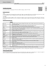
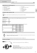
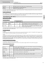
PROCESS SETTINGS
Settings
Settings
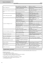
Welding process
Standard
Smooth current
Pulsed
Pulsed current
Spot welding
Smooth tacking
Spot-Pulse
Pulsed tacking
Trigger mode
2T, 4T, Valve
Choice of trigger welding management mode.
Access to some of the welding parameters depends on the selected display mode: Settings/Display mode: Easy or Expert. Refer to the HMI ma
-
nual.
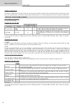
SETTINGS
• Standard
The standard DC TIG welding process allows high quality welding on most ferrous materials such as steel and stainless steel, but also copper and its
alloys including titanium. The various current and gas management possibilities allow you to perfectly control your welding operation, from priming to
the final cooling of your weld seam.
• Pulse
This pulsed current welding mode combines high current pulses (I = welding pulses) with low current pulses (cold I, workpiece cooling pulses). The
pulsed mode allows parts to be assembled while limiting temperature rises and warping. Ideal for on site use.
Example:
The welding current (I) is set to 100 A and % (cold I) = 50%, i.e. cold current = 50% x 100 A = 50.
F(Hz) is set to 10 Hz, the signal period will be 1/10 Hz = 100 ms -> a 100 A pulse every 100 ms then followed by another at 50 A.
• Spot
This welding mode allows the pre-assembly of parts before welding. Spot welding can be done manually using the trigger or timed with a predefined
spot welding period. Spot welding allows for better reproduction and non-oxidised weld points.
• Spot-Pulse
This method of welding is used to pre-assemble thin sheet metal workpieces prior to the actual welding process. Spot welding can be done manually
using the trigger or timed with a predefined spot welding period. Spot welding allows for better reproduction and non-oxidised weld points.
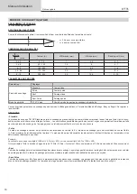
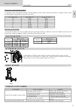
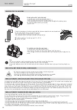
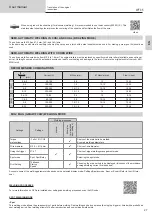
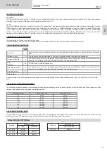
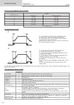
CHOOSING THE ELECTRODE’S DIAMETER
Electrode Ø (mm)
DC TIG
Pure tungsten
Tungsten with oxides
1
10 > 75
10 > 75
1.6
60 > 150
60 > 150
2
75 > 180
100 > 200
2.5
130 > 230
170 > 250
3.2
160 > 310
225 > 330
Approx. = 80 A per mm Ø
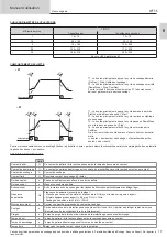
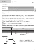
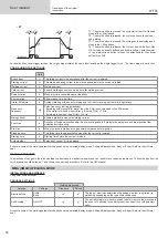
USING THE TRIGGER
• 2T
t
t
t
t
t
t
T2
T1
Main button
T3
T1
Main button
T2
T4
T3
T1
Main button
T2
T4
>0.5s
<0.5s
<0.5s
T1 - The main button is pressed, the welding cycle starts (Pre-Gas,
I_Start, upslope and welding).
T2 - The main button is released, the welding cycle is stopped
(downslope, I_Stop, Post-Gas).
For two-button torches in T2 only, the secondary button is treated as
the main button.

