26
User manual
WF 35
Translation of the original
instructions
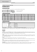
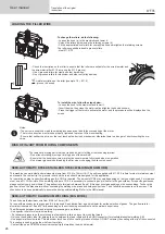
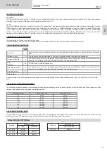
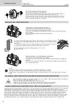
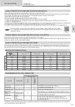
LOADING THE FILLER WIRE
a
b
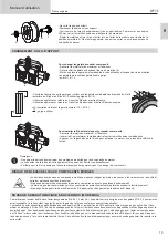
To change the rollers, do the following:
- Loosen the knob (a) to the maximum and lower it.
- Unlock the rollers by removing the retaining screws (b)
- Fit the appropriate drive rollers for your application and retighten the retaining screws.
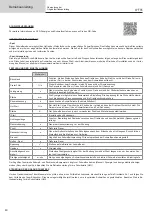
The rollers supplied are double groove rollers :
- steel Ø 1.0/1.2
- Check the inscription on the roller to ensure that the rollers are suitable for the wire diameter and
the wire material (for Ø 1.0 wire, use the Ø 1.0 groove).
- Use V-grooved rollers for steel and other hard wires.
- Use U-grooved rollers for aluminium and other soft, alloyed wires.
: visible inscription on the roller (example: 10 = Ø 1.0)
: groove to be used
a
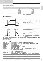
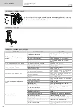
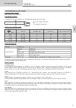
To install the wire, follow the steps below:
- Loosen the knob to the maximum and lower it.
- Insert the wire, then close the motor reel and tighten the knob as shown.
- Press the trigger of the torch to activate the motor, and the procedure will be displayed on the
screen..
Notes:
- Too narrow a sheath can lead to unreeling issues and can lead to the overheating of the motor.
- The torch connection must also be properly tightened to prevent it from overheating.
- Ensure that neither the wire, nor the reel, touches the device’s mechanism, otherwise there is a danger of short-circuiting the ma
-
chine.
RISK OF INJURY FROM MOVING COMPONENTS
The reels have moving parts that can trap hands, hair, clothing or tools causing injuries!
- Do not touch rotating, moving or driving parts of the machine!
• Ensure that the housing covers or protective covers remain fully closed when in operation.
• Do not wear gloves when threading the filler wire or changing the filler-wire’s spool.
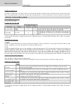
SEMI-AUTOMATIC STEEL/STAINLESS STEEL WELDING (MAG MODE)
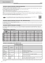
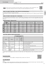
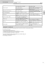
This machine can weld steel and stainless steel wire from Ø 0.6 to 1.2mm (I-A). The unit is supplied with Ø 1.0/1.2 rollers for steel or stainless steel
as standard. The contact tip, the grooved roller, and the torch sheath are designed for this application.
For operation on steel, a specific welding gas (Ar+CO2) is required. The amount of CO2 may vary depending on the type of gas used. For stainless
steel, use a 2% CO2 mixture. When welding with pure CO2, it is necessary to connect a gas pre-heater to the gas cylinder. For specific gas issues,
please contact your gas distributor. The gas flow rate for steel is between 8 and 15 litres per minute depending on the surroundings. To check the
gas flow rate on the manometer without unwinding the welding wire, press and hold push-button n°1 and follow the procedure on the screen. This
check should be done periodically to ensure the best possible welding. Refer to the HMI manual.
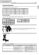
SEMI-AUTOMATIC ALUMINIUM WELDING (MIG MODE)
The unit can weld aluminium wire from Ø 0.8 to 1.2mm (I-B).
For use with aluminium, pure argon gas (Ar) is required. Seek advice from a gas distributor for a wide selection of gases. The gas flow rate for
aluminium is between 15 and 20 l/min depending on the surrounding environment and the welder’s experience.
The differences between steel and aluminium processing are as follows:
- Use specific rollers for aluminium welding.
- Put minimum pressure on the motorised reel’s pressure rollers so as not to crush the thread.
- Only use the capillary tube (for guiding the wire between the feed rollers and the EURO connector) for steel/stainless steel welding (I-B)
- Use a special aluminium torch. This aluminium torch has a Teflon coating to reduce friction. DO NOT cut away the coating at the tip of the connector!
This coating is used to guide the wire from the rollers.
- Contact tips: use a SPECIAL aluminium contact tip that matches the wire’s diameter.

