7 - 57
3. Adjust Sequence Valve 1. This cartridge is one of
the two cartridges located on the top of the
manifold and is silver in color. With the trencher
motor running in reverse and a gage located at the
pump, loosen the lock nut and turn the allen screw
adjustment until the pressure on the gage is 2700
psi. Tighten the lock nut.
7.10 HYDRAULIC CYLINDERS
Disassembly And Inspection
The 3” bore lift arm cylinder is fitted with an external
threaded gland retainer. The 2 1/2” bore Crowd
cylinder is fitted with an internal ring gland retainer. The
following is the procedure for replacing piston rod gland
and piston seals applies to both cylinders. Go to page
61 for removal of the Crowd cylinder internal retaining
ring.
1. Clamp the rear clevis end of the cylinder in a soft
jawed vice. Do not clamp on the cylinder barrel.
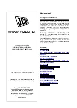
Then unscrew the external gland retaining nut
using a “C” wrench (see below).
2. Remove the gland retaining nut.
3. Pull the piston rod and gland assembly out from
the cylinder barrel with the aid of a bar through the
rod end clevis if necessary until the gland and
piston are clear of the cylinder barrel. The Crowd
cylinder may require very low pressure air (10 psi.
max.) applied to the rear end to assist piston and
gland removal (see below).
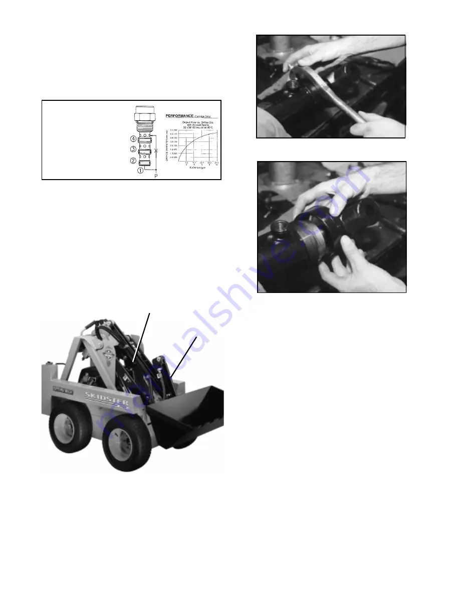
OPERATION OF EC10-40 VALVE
The EC10-40 valve maintains a constant
flow rate from (3) regardless of load pres-
sure changes in the circuit downstream of
(3).
The cartridge maintains a constant differen-
tial pressure from circuit point P to port (3),
thereby regulating the hydraulic flow rate
between the two points in the circuit. This
valve is a priority type regulator, delivering
pump flow first to (3), then by-passing ex-
cess to (2). All ports may be fully pressur-
ised.
CARTRIDGE DETAILS
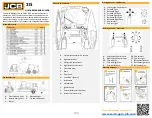
Lift Arms Cylinder
Crowd Cylinder
Summary of Contents for 950001
Page 1: ......
Page 11: ......
Page 15: ......
Page 16: ......
Page 19: ......
Page 65: ...8 65...
Page 66: ...8 66...


