215
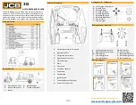
QUICK REFERENCE GUIDE
This Quick Reference Guide DOES NOT replace the Operators
Manual. You MUST read ALL the disclaimers and safety and other
instructions in the Operators Manual before initially operating this
product. Accordingly, no legal claims can be entertained based on
the data, illustrations or descriptions in this Quick Reference Guide.
Access additional information
Driving Controls
–
ISO Pattern
Start Up Sequence
Static Dimensions
Tie Down Points
Cab and Switch Panel
Driving Controls
–
H Pattern
A. Left armrest (contains 12V socket)
B. Right interlock bar
C. Left joystick control lever
D. Right joystick control lever
E.
Left switch panel
F.
Radio
G. Front panel
H. Cab HVAC (optional)
J.
Instruments
K. Hand throttle
L.
Ignition Switch
P.
Foot throttle control (optional)
Q. Interior rear view mirror
A. Front tie down point
B. Rear tie down points
C. Blocks
D. Machine height
E.
Tie down point label
A. Left Joystick Control Level
B. Forward Drive
C. Backward Drive
D. Forward Left Drive
E.
Forward Right Drive
F.
Backward Left Drive
G. Backward Right Drive
H. Spin turn left
J.
Spin turn right
Left Joystick Control Lever
Right Joystick Control Lever
Forward drive
Forward Right drive
Forward left drive
A.
B.
CD.
C.
D.
Spin turn left
Spin turn right
Backwards left drive
Backwards right drive
Backwards drive
DE.
CF.
F.
E.
EF.
Revision 1.0
12/2/2020


