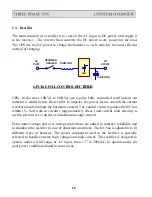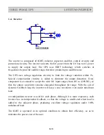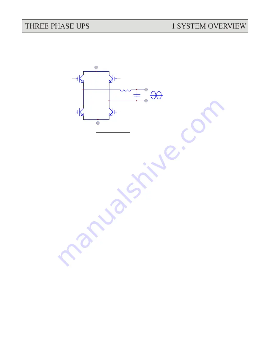
1.4. Inverter
DC-
AC
AC
DC+
IGBT INVERTER
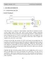
The inverter is composed of IGBT, inductor, capacitor, snubber, control circuitry and
protection circuitry. The inverter converts the DC power from the DC bus to AC power
to supply the output load. The UPS uses IGBT technology which switches at
frequencies beyond the audible range, therefore producing no audible noise.
The UPS uses voltage regulation circuitry to limit the voltage variation within 1%.
Special compensation circuitry is added to eliminate the output distortion. Every
component is oversized to accept the wide DC input range (from 285 to 420VDC), so
that the output waveform remains sinusoidal throughout the range. With the aid of
dynamic feedback loop the inverter will keep a sine waveform even under non-linear
load.
An independent inverter is used for each phase. Although it is more expensive, each
inverter has its independent feedback, so that the voltage is unaffected when load is
added to the adjacent phase, producing excellent voltage regulation under 100%
unbalanced load.
The IGBT is operated in its optimal condition to obtain best efficiency, so as to
minimize the power cost of the user.
1-10
Summary of Contents for T3UPS-33-700K
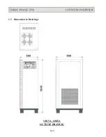
Page 18: ...1 7 Dimension Drawings 10KVA 60KVA OUTLINE DRAWING 1 13 ...
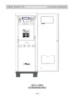
Page 19: ...10KVA 60KVA INTERIOR DRAWING 1 14 ...
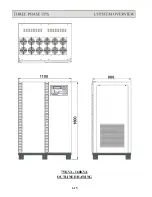
Page 20: ...75KVA 160KVA OUTLINE DRAWING 1 15 ...
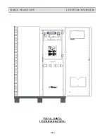
Page 21: ...75KVA 160KVA INTERIOR DRAWING 1 16 ...
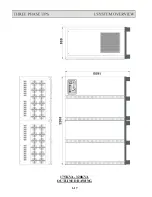
Page 22: ...175KVA 320KVA OUTLINE DRAWING 1 17 ...
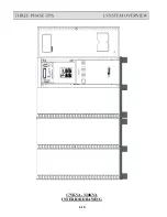
Page 23: ...175KVA 320KVA INTERIOR DRAWING 1 18 ...
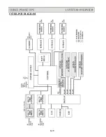
Page 24: ...INTER PCB DIAGRAM 1 19 ...
Page 31: ...1 ...
Page 35: ...3 3 ...
Page 70: ...ONE TO TWO SERIAL REDUNDANCY 8 3 ...
Page 77: ...Appendices Additional Data on Options UPSCOMTM UPSCALLTM DCMANTM ...
Page 80: ...3 ...
Page 81: ......


