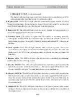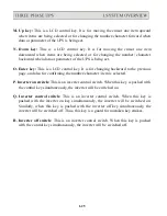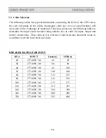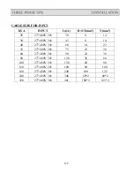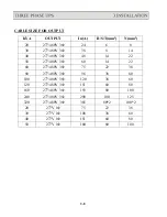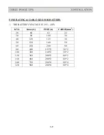
110% LOAD –
load connected to the output is over 110% of the UPS rating.
125% LOAD –
load connected to the output is over 125% of the UPS rating.
150% LOAD –
load connected to the output is over 150% of the UPS rating.
RESERVE AC FAIL –
reserve AC magnitude is out of range.
RESERVE FREQ FAIL –
reserve frequency is out of range.
BATTERY LOW –
DC bus (or battery) is lower than 320VDC, low battery
shutdown is approaching.
BATTERY LOW SHUTDOWN –
inverter shutdown due to DC bus (or battery)
lower than 295VDC (lower than the acceptable DC voltage of the inverter).
RECT AC FAIL –
rectifier AC magnitude is out of range.
ROTATION ERROR –
rectifier AC phase rotation is incorrect.
RECTIFIER SHUTDOWN –
rectifier shutdown due to DC bus too high (over
445VDC), will automatically restart 30 seconds after abnormal situation has
been cleared.
HIGH DC –
DC voltage over 430VDC and the bus voltage will be limited at
this voltage.
BOOST CHARGE –
the batteries are being boost charged by the rectifier.
BATTERY TEST –
batteries are being tested.
EMERGENCY STOP –
inverter shutdown due to emergency stop switch
pushed.
DATA LINE –
blinks when data is transmitted to or received from the
communication port.
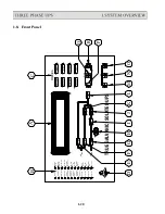
C: Warning LEDs:
When abnormal condition happens, these LEDs will light to warn
the user according to the cause of the faulty condition. Therefore all these LEDs
should be extinguished under normal condition. These LEDs are as shown below:
RECT AC FAIL –
rectifier AC input is abnormal either due to AC magnitude
out of the range or phase rotation error, rectifier shutdown.
RESERVE FAIL –
reserve AC input is abnormal either due to AC magnitude
out of range or frequency out of range.
FUSE/TEMP –
Inverter fuse is blown or over temperature condition exists.
1-22
Summary of Contents for T3UPS-33-700K
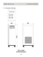
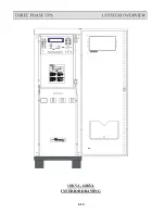
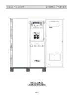
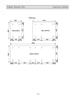
Page 18: ...1 7 Dimension Drawings 10KVA 60KVA OUTLINE DRAWING 1 13 ...
Page 19: ...10KVA 60KVA INTERIOR DRAWING 1 14 ...
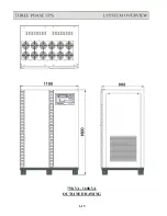
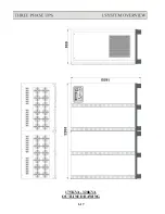
Page 20: ...75KVA 160KVA OUTLINE DRAWING 1 15 ...
Page 21: ...75KVA 160KVA INTERIOR DRAWING 1 16 ...
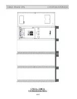
Page 22: ...175KVA 320KVA OUTLINE DRAWING 1 17 ...
Page 23: ...175KVA 320KVA INTERIOR DRAWING 1 18 ...
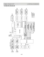
Page 24: ...INTER PCB DIAGRAM 1 19 ...
Page 31: ...1 ...
Page 35: ...3 3 ...
Page 70: ...ONE TO TWO SERIAL REDUNDANCY 8 3 ...
Page 77: ...Appendices Additional Data on Options UPSCOMTM UPSCALLTM DCMANTM ...
Page 80: ...3 ...
Page 81: ......

