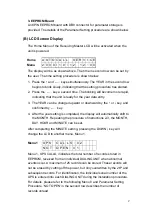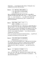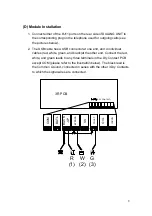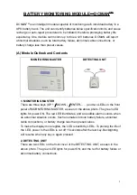
Menu 6
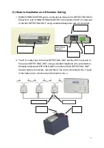
P R I O R I T Y : 1
N O . O F
C A L L S : 0 1
Menu 6, the PRIORITY menu, displays the priority of the phone number
that the DIALING UNIT chooses to call when abnormal events occur. The
priority is set from 1 to ’. Please refer to Menu 12 for priority setting
instructions. NO. OF CALLS in the second row indicates the number of
times this number has been redialed before the connection is established.
Pressing the
↓
key changes the LCD to Menu 7. Pressing the
←┘
key
returns the LCD to Menu 3.
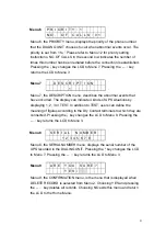
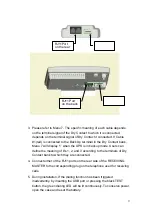
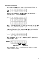
Menu 7
D
E
S
C
R I P T I O N
1
Menu 7, the DESCRIPTION menu, describes the abnormal events that
have occurred. The display can indicate 4 kinds of UPS situations by
displaying 1, 2, 3 or TEST. In addition to TEST, users can define the
meaning of figures according to the Dry Contact terminals to which they are
connected. Pressing the
↓
key changes the LCD to Menu 8. Pressing the
←┘
key returns the LCD to Menu 3.
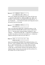
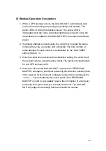
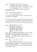
Menu 8
S E R I A L N U M B E R
1 2 3 4 5 6 7 8
Menu 8, the SERIAL NUMBER menu, displays the serial number of the
UPS recorded in the DIALING UNIT. Pressing the
↑
key changes the LCD
to Menu 7. Pressing the
←┘
key returns the LCD to Menu 3.
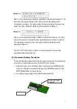
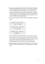
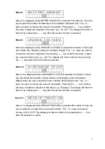
Menu 9
A R E Y O U
S U R E ?
Y E S / N O
Menu 9, the CONFIRMATION menu, is the menu that is displayed when
DELETE RECORD is selected from Menu 2. Choosing YES and pressing
the
←┘
key deletes all records. Choosing NO exits this menu and return
the LCD to the Home Menu.
4
Summary of Contents for T3UPS-33-700K
Page 18: ...1 7 Dimension Drawings 10KVA 60KVA OUTLINE DRAWING 1 13 ...
Page 19: ...10KVA 60KVA INTERIOR DRAWING 1 14 ...
Page 20: ...75KVA 160KVA OUTLINE DRAWING 1 15 ...
Page 21: ...75KVA 160KVA INTERIOR DRAWING 1 16 ...
Page 22: ...175KVA 320KVA OUTLINE DRAWING 1 17 ...
Page 23: ...175KVA 320KVA INTERIOR DRAWING 1 18 ...
Page 24: ...INTER PCB DIAGRAM 1 19 ...
Page 31: ...1 ...
Page 35: ...3 3 ...
Page 70: ...ONE TO TWO SERIAL REDUNDANCY 8 3 ...
Page 77: ...Appendices Additional Data on Options UPSCOMTM UPSCALLTM DCMANTM ...
Page 80: ...3 ...
Page 81: ......

