5-11
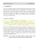
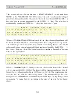
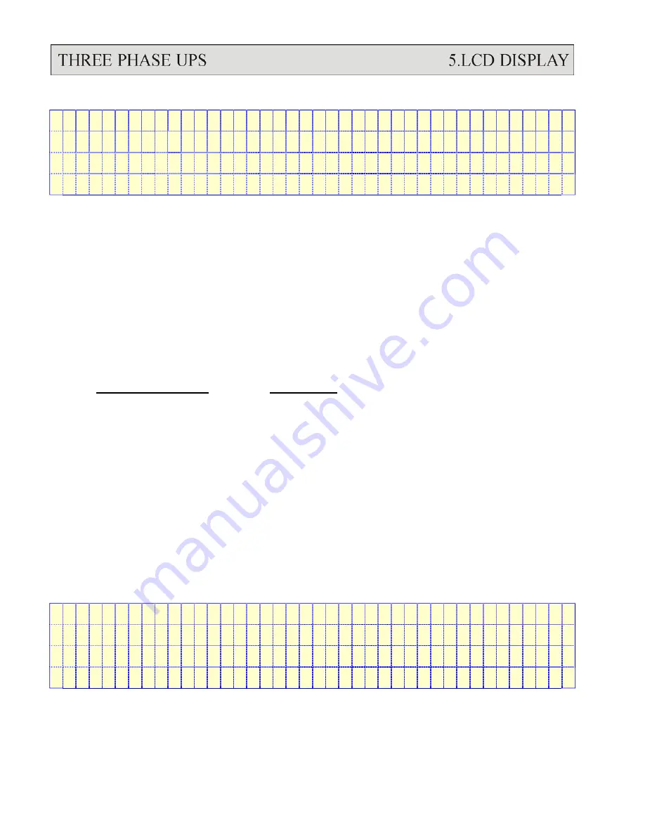
<
B O O S T C H A R G E
S E T T I N G
>
A U T O - B O O S T ( M O N T H ) = 0 4
A U T O - B O O S T ( B A T T L O W ) = 0 4
→
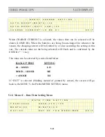
C H A R G E C U R R E N T = L O
M E
H I
E X I T
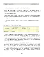
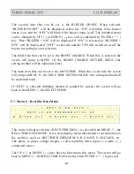
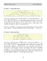
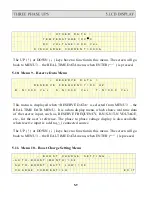
When CHARGE CURRENT is selected, the values that can be selected will be
shown (LO/ME/HI). When the batteries are being boost-charged for whatever the
reason, the charging current will be limited by a value according the setting in this
row. The current value (or the being selected) will flash, and is confirmed by the
ENTER (
←┘
) key.
The value can be selected by a rules listed below:
BACK-UP TIME SETTING
10 – 30 MIN LO
30MIN – 1HOUR ME
> 1 HOUR HI
If “EXIT” is selected (blinking instead of pointed by cursor), the screen will go
back to the MENU 5- the PARAMETER SETTING menu.
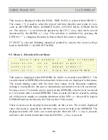
5.12. Menu 11 – Date/Time Setting Menu
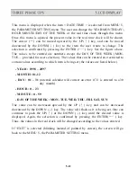
<
D A T E
T I M E
S E T T I N G
>
→
Y E A R = X X X X
H O U R ( 2 4 H ) = X X
M O N T H = X X
M I N U T E = X X
D A Y = X X
D A Y
O F
T H E
W E E K = M O N
E X I T
Summary of Contents for T3UPS-33-700K
Page 18: ...1 7 Dimension Drawings 10KVA 60KVA OUTLINE DRAWING 1 13 ...
Page 19: ...10KVA 60KVA INTERIOR DRAWING 1 14 ...
Page 20: ...75KVA 160KVA OUTLINE DRAWING 1 15 ...
Page 21: ...75KVA 160KVA INTERIOR DRAWING 1 16 ...
Page 22: ...175KVA 320KVA OUTLINE DRAWING 1 17 ...
Page 23: ...175KVA 320KVA INTERIOR DRAWING 1 18 ...
Page 24: ...INTER PCB DIAGRAM 1 19 ...
Page 31: ...1 ...
Page 35: ...3 3 ...
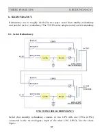
Page 70: ...ONE TO TWO SERIAL REDUNDANCY 8 3 ...
Page 77: ...Appendices Additional Data on Options UPSCOMTM UPSCALLTM DCMANTM ...
Page 80: ...3 ...
Page 81: ......

