(g) Plug & Play Modular design:
The power circuit is separated into several
modules plugged into slots in the UPS, which are easy to pull out, permitting
quick maintenance and easier trouble shooting.
(h) Cold start function:
the UPS can be started without an AC source, that is, can
be started with battery power only. This is possible because current limit
circuitry is added, preventing the problem of large inrush current blowing the
battery fuse and damaging the DC capacitors when batteries are connected to an
empty DC bus (before the DC bus is energized).
(i) Multi-CPU design:
Several CPUs are employed in the control circuit, and
critical functions are designed with parallel redundancy to improve reliability.
Therefore, in case of one CPU failure, the other CPUs keep the UPS operational,
and the output AC is not affected.
(j) Protection against misuse:
The UPS is designed with breaker on/off sensor,
power supply sensor, etc. Therefore, any operational mistake made by the user
causes no harm to the UPS.
(k) Accepts wide input range:
The UPS is designed to accept a wide input range,
so that it can work effectively under an unstable AC source. All of the input
components used are specifically selected to handle extreme high voltage and high
current.
(l) Operating environment:
Each component of the UPS is chosen with large
safety margin to accommodate extreme environments, such as temperature,
humidity, altitude, shock or contamination.
(m) Intelligent charger:
The UPS will automatically recharge (boost charge) the
batteries every time the batteries are depleted to a voltage level equal to 2V/Cell.
Thus, the batteries can be restored to full capacity as soon as possible, and made
ready for the next back-up requirement. In order to keep the batteries in the best
condition, the UPS will boost charge the batteries for several hours (selectable)
automatically every month. To avoid over charging the batteries, boost charge will
stop when the ambient temperature is over 35
o
C (95
o
F)
1-6
Summary of Contents for T3UPS-33-700K
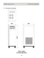
Page 18: ...1 7 Dimension Drawings 10KVA 60KVA OUTLINE DRAWING 1 13 ...
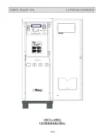
Page 19: ...10KVA 60KVA INTERIOR DRAWING 1 14 ...
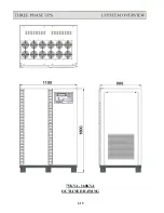
Page 20: ...75KVA 160KVA OUTLINE DRAWING 1 15 ...
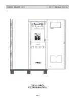
Page 21: ...75KVA 160KVA INTERIOR DRAWING 1 16 ...
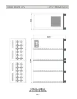
Page 22: ...175KVA 320KVA OUTLINE DRAWING 1 17 ...
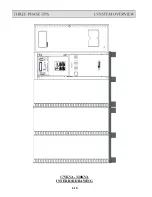
Page 23: ...175KVA 320KVA INTERIOR DRAWING 1 18 ...
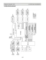
Page 24: ...INTER PCB DIAGRAM 1 19 ...
Page 31: ...1 ...
Page 35: ...3 3 ...
Page 70: ...ONE TO TWO SERIAL REDUNDANCY 8 3 ...
Page 77: ...Appendices Additional Data on Options UPSCOMTM UPSCALLTM DCMANTM ...
Page 80: ...3 ...
Page 81: ......


