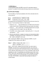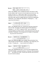
Menu 13 S E R I A L N U M B E R
1 2
3
4
5
6
7 8
Menu 13 is accessed when SERIAL NUMBER is selected from Menu 10. In
this menu, the serial number of the UPS, to which the dialing unit is
connected, is entered. The total number of digits should not be more than
eight. The entry method is identical to that specified in Menu 11.
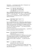
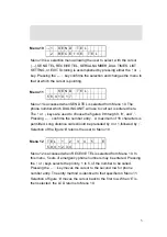
Menu 14
D
I
A
L
T I M E S
1
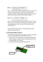
Menu 14 is accessed when DIAL TIMES is selected from Menu 10. In this
menu, the number of redials for each specified phone number, is entered.
The maximum number is nine. The entry method is identical to that
specified in Menu 11.
The LIST SETTING option in Menu 10 can be selected to review the
parameters that have been set.
(C) Parameter Setting Procedure
To prevent damage, please follow the procedures below for the initial setup,
or revision, of parameters revision of the UPSCALL module.
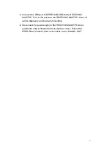
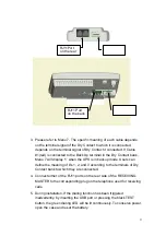
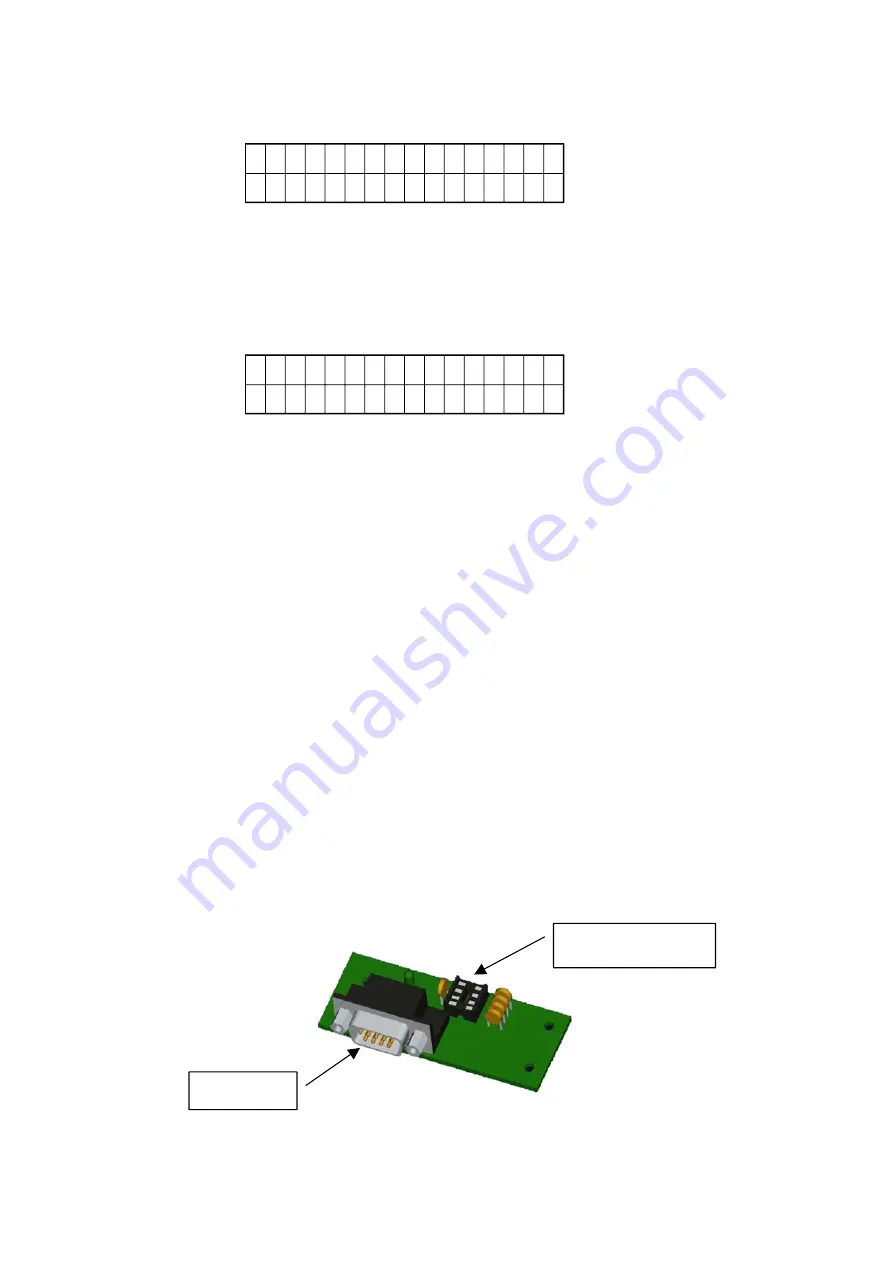
1. Open the cover of the DIALING UNIT, locate the 8 pin EEPROM, and
remove it. Plug this component into the 8 pin EEPROM socket on the
EEPROM BOARD, as shown below.
2. Cut off the power supply of the RECEIVING MASTER.
DB9 Port
8PIN EEP ROM
Socket
6
Summary of Contents for T3UPS-33-700K
Page 18: ...1 7 Dimension Drawings 10KVA 60KVA OUTLINE DRAWING 1 13 ...
Page 19: ...10KVA 60KVA INTERIOR DRAWING 1 14 ...
Page 20: ...75KVA 160KVA OUTLINE DRAWING 1 15 ...
Page 21: ...75KVA 160KVA INTERIOR DRAWING 1 16 ...
Page 22: ...175KVA 320KVA OUTLINE DRAWING 1 17 ...
Page 23: ...175KVA 320KVA INTERIOR DRAWING 1 18 ...
Page 24: ...INTER PCB DIAGRAM 1 19 ...
Page 31: ...1 ...
Page 35: ...3 3 ...
Page 70: ...ONE TO TWO SERIAL REDUNDANCY 8 3 ...
Page 77: ...Appendices Additional Data on Options UPSCOMTM UPSCALLTM DCMANTM ...
Page 80: ...3 ...
Page 81: ......

