
1.
SYSTEM OVERVIEW
1.1. Construction of the UPS
General Topology
:
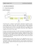
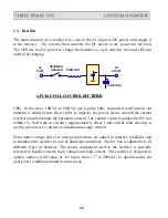
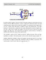
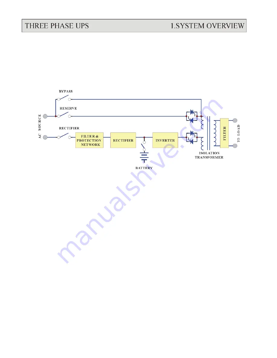
The UPS system is composed of input breakers, input filter & protection network,
rectifier, battery bank, inverter, static switch, bypass breaker, isolation transformer
and output filter. The basic topology is shown in the diagram above. Under normal AC
mode, energy from the AC source is converted to DC power and supplied to the
inverter to charge the batteries to its full capacity all the time, ready to support the
output load in case of AC source failure.
Although the principle and operation of a UPS seems simple and straightforward, the
requirement for a reliable and intelligent UPS makes the design and manufacturing of
a high power UPS one requiring advanced technology, intelligence, experience and
most important, consideration of the user interface. Many years have been spent in
designing the most rugged, intelligent and reliable UPS for the market, and a safe and
convenient UPS for the user.
Choosing the best and most suitable UPS for a given application can be easy or
difficult, depending on the client’s knowledge of key parameters. The most obvious
specification, output power, depends on the size of the load. Often, an allowance of
50% more power is added to the present load requirement, both for tolerance and for
future expansion.
1-1
Summary of Contents for T3UPS-33-700K
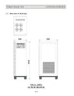
Page 18: ...1 7 Dimension Drawings 10KVA 60KVA OUTLINE DRAWING 1 13 ...
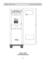
Page 19: ...10KVA 60KVA INTERIOR DRAWING 1 14 ...
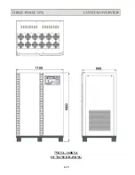
Page 20: ...75KVA 160KVA OUTLINE DRAWING 1 15 ...
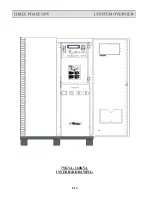
Page 21: ...75KVA 160KVA INTERIOR DRAWING 1 16 ...
Page 22: ...175KVA 320KVA OUTLINE DRAWING 1 17 ...
Page 23: ...175KVA 320KVA INTERIOR DRAWING 1 18 ...
Page 24: ...INTER PCB DIAGRAM 1 19 ...
Page 31: ...1 ...
Page 35: ...3 3 ...
Page 70: ...ONE TO TWO SERIAL REDUNDANCY 8 3 ...
Page 77: ...Appendices Additional Data on Options UPSCOMTM UPSCALLTM DCMANTM ...
Page 80: ...3 ...
Page 81: ......