1.3
. Rect
ifi
e
r
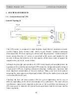
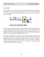
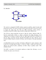
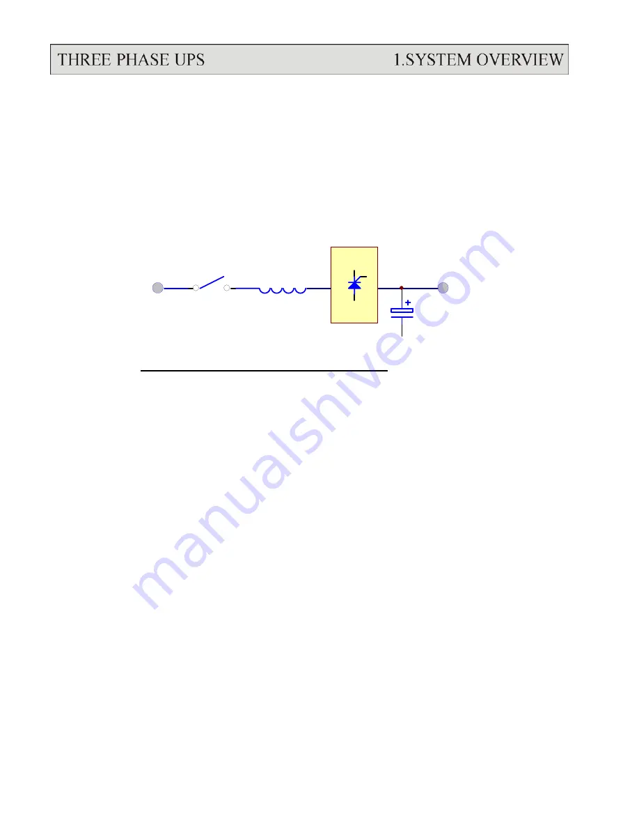
The main function of a rectifier is to convert the AC input to DC power, and supply it
to the inverter. The inverter then converts the DC power to AC power for the load.
The UPS use the DC power to charge the batteries as well, which is the most efficient
method of charging.
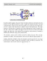
RECTIFIER
AC
SCR
DC
BREAKER
INDUCTOR
INPUT
OUTPUT
CAPACITOR
6-PULS E FULL CONTROL RECTIFIER
UPSs in the sizes 10KVA to 80KVA use 6-pulse fully controlled rectification. An
inductor is added before the rectifier to improve the power factor, smooth the current
waveform and eliminate the harmonic current. The control circuit regulates the DC bus
within 1%. Soft walk-in circuitry (approximately 20sec.) and current limit circuitry is
used to prevent over current or instantaneous surge current.
Extra under-voltage and over-voltage protections are added to improve reliability and
to shutdown the rectifier in case of abnormal conditions. The DC bus is adjustable to fit
different types of batteries. The power component used in the rectifier is specially
selected to handle extreme high voltage and high current. The rectifier is designed to
operate under a wide range of AC input, from 177 to 300VAC, to operate under the
poor power conditions found in some areas.
1-8
Summary of Contents for T3UPS-33-700K
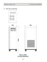
Page 18: ...1 7 Dimension Drawings 10KVA 60KVA OUTLINE DRAWING 1 13 ...
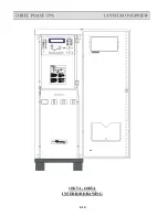
Page 19: ...10KVA 60KVA INTERIOR DRAWING 1 14 ...
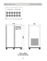
Page 20: ...75KVA 160KVA OUTLINE DRAWING 1 15 ...
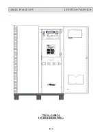
Page 21: ...75KVA 160KVA INTERIOR DRAWING 1 16 ...
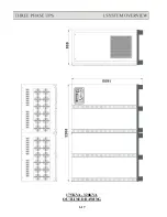
Page 22: ...175KVA 320KVA OUTLINE DRAWING 1 17 ...
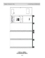
Page 23: ...175KVA 320KVA INTERIOR DRAWING 1 18 ...
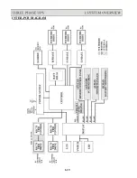
Page 24: ...INTER PCB DIAGRAM 1 19 ...
Page 31: ...1 ...
Page 35: ...3 3 ...
Page 70: ...ONE TO TWO SERIAL REDUNDANCY 8 3 ...
Page 77: ...Appendices Additional Data on Options UPSCOMTM UPSCALLTM DCMANTM ...
Page 80: ...3 ...
Page 81: ......


