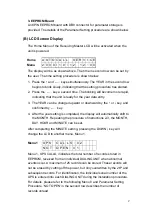
(B) LCD Screen Display
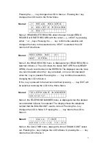
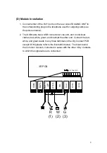
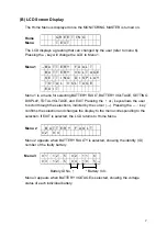
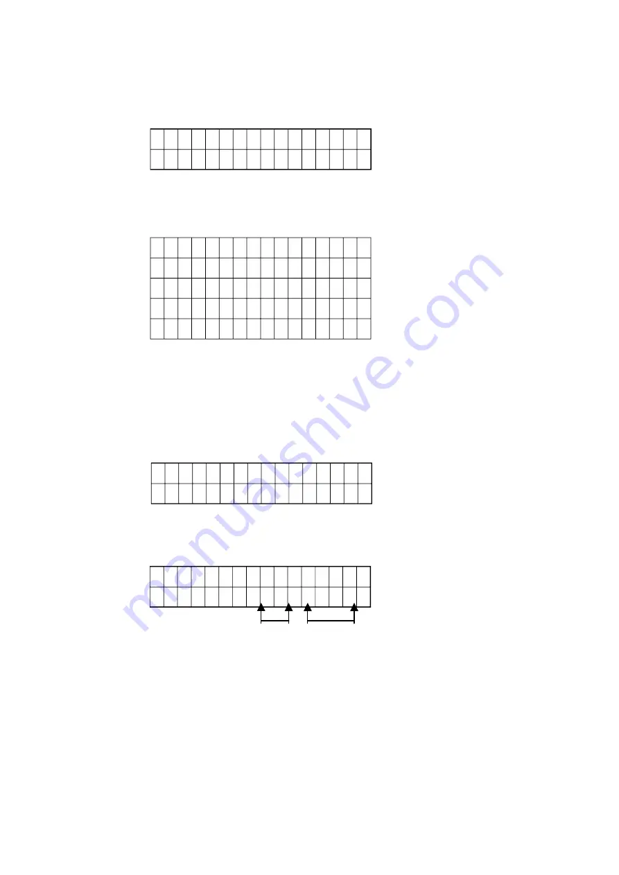
The Home Menu is displayed once the MONITORING MASTER is turned on..
Home
Menu
G
R
E
E T I N G
T
E
X
T
The LCD displays a greeting that can changed by the user (refer to menu 6).
Pressing the
↓
key will change the LCD to Menu 1.
Menu 1
→
B A T T E R Y
F A U L T
B A T T E R Y
V O L T A G E
S E T T I N G
D I S P L A Y
T O T A L V O L T A G E
E
X I T
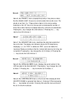
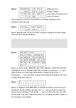
Menu 1 is a menu for selecting BATTERY FAULT, BATTERY VOLTAGE, SETTING
DISPLAY, TOTAL VOLTAGE, and EXIT. Pressing the
↑
or
↓
keys allows the user
to scroll through the selections, indicted by the cursor (
→
). Pressing the
←┘
key
confirms the selection and changes the display to the menu corresponding to the
selection. If EXIT is selected, the LCD returns to Home Menu.
Menu 2
B A T T E R Y
F A U L T
0 2
0 4
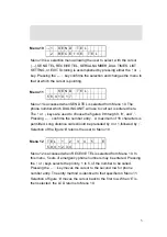
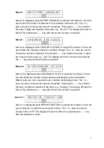
Menu 2 appears when BATTERY FAULTY is selected, showing the identity (ID)
number of the faulty battery.
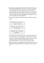
Menu 3
0 1 : 1 2 . 5 0 2 : 1 1 . 6
0 3 : 1 2 . 5 0 4 : 1 0 . 5
→
Battery ID No.
↑
↑
Battery Vdc
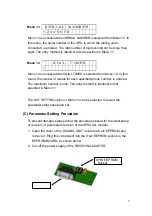
Menu 3 appears when BATTERY VOLTAGE is selected, showing the voltage
status of each individual battery.
2
Summary of Contents for T3UPS-33-700K
Page 18: ...1 7 Dimension Drawings 10KVA 60KVA OUTLINE DRAWING 1 13 ...
Page 19: ...10KVA 60KVA INTERIOR DRAWING 1 14 ...
Page 20: ...75KVA 160KVA OUTLINE DRAWING 1 15 ...
Page 21: ...75KVA 160KVA INTERIOR DRAWING 1 16 ...
Page 22: ...175KVA 320KVA OUTLINE DRAWING 1 17 ...
Page 23: ...175KVA 320KVA INTERIOR DRAWING 1 18 ...
Page 24: ...INTER PCB DIAGRAM 1 19 ...
Page 31: ...1 ...
Page 35: ...3 3 ...
Page 70: ...ONE TO TWO SERIAL REDUNDANCY 8 3 ...
Page 77: ...Appendices Additional Data on Options UPSCOMTM UPSCALLTM DCMANTM ...
Page 80: ...3 ...
Page 81: ......

