6–108
345 TRANSFORMER PROTECTION SYSTEM – INSTRUCTION MANUAL
S3 PROTECTION
CHAPTER 6: SETPOINTS
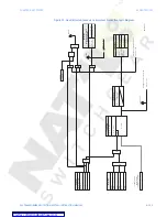
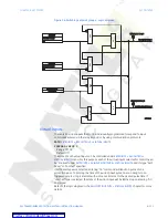
Figure 32: Negative Sequence Timed Overcurrent logic diagram
Calculated
Negative
Sequence
Current
SETPOINT
NEG
SEQ
T
O
C
FUNCTN
:
Disabled
=
0
Latched
Alarm
AND
LED:
TRIP
Alarm
OR
OR
AND
SETPOINTS
Operate
output
relays
upon
selection
OUTPUT
RELA
Y
4
OUTPUT
RELA
Y
5
OUTPUT
RELA
Y
6
OUTPUT
RELA
Y
3
T
rip
AND
T
o
Breaker
Failure
T
rip
SETPOINTS
BLOCK
1:
Of
f
=
0
BLOCK
2:
Of
f
=
0
BLOCK
3:
Of
f
=
0
OR
LED:
PICKUP
Message
and
Event
Recorder
Message
and
Event
Recorder
I_
2
LED:
ALARM
RESET
Command
AND
S
R
LA
TCH
SETPOINTS
RUN
NEG
SEQ
TO
C
PICKUP
NEG
SEQ
T
O
C
CUR
VE
NEG
SEQ
T
O
C
TDM
I_
2
>
PICKUP
Adjust
PKP
NEG
SEQ
T
O
C
RESET
I_
2
x
t
=
NEG
SEQ
TO
C
O
P
SETPOINTS
(configurable
only
if
“TRIP”
function
selected
)
Operate
trip
output
relays
upon
selection
RL
Y
2
TRIP
W
2
BKR
RL
Y
1
TRIP
W
1
BKR
NEG
SEQ
T
O
C
PKP
897807.
cdr

