6–106
345 TRANSFORMER PROTECTION SYSTEM – INSTRUCTION MANUAL
S3 PROTECTION
CHAPTER 6: SETPOINTS
Negative sequence
timed overcurrent
protection
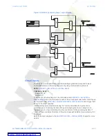
The 345 relay has two Negative Sequence Overcurrent elements per setpoint group. The
negative sequence overcurrent protection responds to negative sequence |
I
2
|current,
where it is calculated as .
The negative sequence overcurrent elements are uniquely suited to detect phase-phase
faults and are not sensitive to balanced loads. While negative sequence elements do not
respond to a balanced load, they do detect the negative sequence current present in an
unbalanced load. For this reason, select an element pickup setting above the maximum
expected
I
2
current due to load unbalance.
PATH
:
SETPOINTS > S3 PROTECTION > SETPOINT GROUP 1(2) > NEG SEQ TOC1(2)
NEG SEQ TOC1(2) FUNC
Range: Disabled, Latched Alarm, Alarm, Trip
Default: Disabled
The selection of the
Latched Alarm
,
Alarm
, or
Trip
setting enables the Negative
Sequence TOC function. The output relay #1 “Trip” will operate if the function
Trip
is
selected, and the negative sequence current computed by the relay, is above the NEG
SEQ TOC PKP setting for a time greater than the selected time under NEG SEQ TOC
DELAY. The “ALARM” LED will not turn on if the negative sequence TOC function is set to
Trip
. The “ALARM” LED will flash under the neg. sequence TOC operating condition, with
the negative sequence TOC function selected as
Alarm
, and will self-reset when this
operating condition clears. Until a reset command is initiated, if
Latched Alarm
is
selected as a negative sequence TOC function, the “ALARM” LED will flash during the TOC
condition, and will stay “ON” after the condition clears. The output relay #1 “Trip” will not
operate if the
Latched Alarm
or
Alarm
setting is selected. Any or all of the output relays
3 to 6 can be selected to operate with the negative sequence TOC function selected as
Latched Alarm
,
Alarm
, or
Trip
.
PHASE CT INPUTS
Range: CT(W1), CT(W2)
Default: CT(W1)
The Negative Sequence TOC menu provides selection for either CT(W1) input currents or
CT(W2) currents. If CT(W1) is selected, the NEG SEQ TOC element will use CT ratings
associated with transformer winding 1. If the CT(W2) setting is selected, the relay will use
the CT ratings associated with transformer winding 2.
NEG SEQ TOC1(2) PKP
Range: 0.04 to 20.00 x CT in steps of 0.01 x CT
Default: 0.50 x CT
This setting defines the negative sequence TOC pickup level associated with the ratings
of the CTs selected under NEG SEQ CT INPUT.
For example if CT(W1) = 100:5, and the CT(W2)=500:5, a pickup of 0.5 xCT with NEG SEQ
CT INPUT = CT(W1) will be equivalent to a pickup of 0.5x100 = 50Amps negative
sequence current. The same pickup setting with NEG SEQ CT INPUT selected as CT(W2)
will lead to a pickup threshold of 250 Amps neg. sequence current
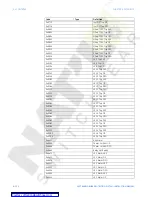
NEG SEQ TOC1(2) CURVE
Range: - ANSI Extremely/Very/Moderately/Normally Inverse- Definite Time- IEC Curve A/B/
C and Short Inverse- IAC Extremely/Very/Inverse/Short
Default: Ext Inverse
This setting defines the shape of the selected overcurrent inverse curve.


