CHAPTER 6: SETPOINTS
S3 PROTECTION
345 TRANSFORMER PROTECTION SYSTEM – INSTRUCTION MANUAL
6–69
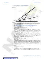
BREAK 1
Range: 0.50 to 4.00xCT in steps of 0.01xCT
Default: 1.50xCT
The setting for Breakpoint 1 defines the limit of linear operation of Winding 1 CT,
accounting for up to 80% of residual flux that effectively reduces the capability of the CT
by a factor of 5. Breakpoint 1 should be set below the current that would cause CT
saturation due to DC components and/or residual magnetism. Very often the Breakpoint
1 setting is based on the transformer Winding 1 nominal current (100% transformer
loading). In such cases, one should check whether or not this setting complies with the
above recommendation regarding the CT linear performance. This breakpoint marks
the end of slope 1, where no CT saturation is expected to restrain (through) currents
smaller than that breakpoint.
BREAK 2
Range: 1.00 to 10.00xCT in steps of 0.01xCT
Default: 1.5xCT
Breakpoint 2 should be set below the fault current that is most likely to saturate any of
the transformer CTs due to an AC component alone. The setting is expressed in times CT
primary of Winding 1. For example if 10 kA is the maximum AC through fault current
before Winding 2 CT (1000:5) starts to saturate, on a 5 MVA transformer with a ratio of
13.8kV/4.16kV, and a Winding1 CT (500:5) rating, the Breakpoint 2 setting will be:
10kA/500 = 20
M(W2) = (4.16kV*500)/(13.8kV*1000) = 0.15 – magnitude compensation factor for
Winding 2 currents
Breakpoint 2 = 20*0.15= 3 xCT
SLOPE 2
Range: 50 to 100% in steps of 1
Default: 95%
The Slope 2 setting ensures stability during fault conditions of the type that produce CT
saturation and spurious high differential current. Slope 2 should be set high to cater for
the worst case scenario where one set of CTs saturates, but the other set does not. In
such cases the differential/restraint ratio can go as high as 95% to 98%.
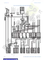
INRUSH INHBT FUNCT
Range: Disabled, 2nd Harm Block
Default: 2nd Harm Block
This setting enables or disables the inrush inhibit function. None of the settings for inrush
inhibit are active when the function is set to “Disabled”.
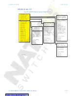
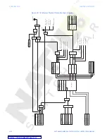
Figure 19: Transformer Inrush inhibiting

