6–128
345 TRANSFORMER PROTECTION SYSTEM – INSTRUCTION MANUAL
S4 CONTROLS
CHAPTER 6: SETPOINTS
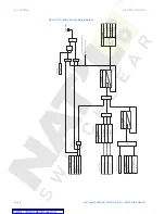
Figure 37: Breaker Failure logic diagram
SE
TP
OINT
Phase
A
curr
ent
(Ia)
SE
TP
OINT
BF
FUNCTION
Disabled
=
0
Latched
Alarm
BF
CURRENT
:
Phase
B
c
urr
ent
(Ib)
Phase
C
curr
ent
(Ic)
Alarm
OR
OR
Trip
Phase
Curr
ents
AND
Ia
>
PICKUP
OR
AND
SE
TP
OINT
BF
E
X
T
INITIA
TE
O
ff=0
Range:
Contact
Input
,
Vir
tual
Input
,R
emot
e
Input
,
Logic
Element
Fr
om
Pr
ot
ection
operation
OR
BF
TIME
DEL
AY
1
SE
TP
OINT
t
PKP
RUN
BF
TIME
DEL
AY
2
SE
TP
OINT
t
PKP
RUN
LED:
AL
ARM
RESE
T
Command
AND
S
R
LA
TC
H
SE
TP
OINTS
Operate
output
relays
upon
selection
OUTPUT
REL
AY
4
OUTPUT
REL
AY
5
OUTPUT
REL
AY
6
OUTPUT
REL
AY
3
Message
and
Ev
ent
Recor
der
W1(W2)
Br
eaker
Failur
e
Ib
>
PICKUP
Ic
>
PICKUP


