CHAPTER 6: SETPOINTS
S3 PROTECTION
345 TRANSFORMER PROTECTION SYSTEM – INSTRUCTION MANUAL
6–83
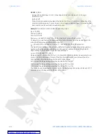
Phase timed
overcurrent
protection
TIME OVERCURRENT CURVE CHARACTERISTICS
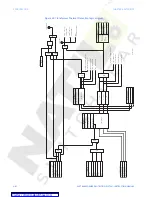
The 345 relay has two setpoint groups. When ordering the relay the user can select each
group to have two phase time overcurrent 51P(2), two ground time overcurrent 51G(2), two
neutral time overcurrent 51N(2), and two negative sequence time overcurrent 51_2(2)
elements. The programming of these elements is identical: PKP, Inverse Curve selection,
and Time Dial Multiplier (TDM). The curve shape can be either a standard curve selected
from a range of standard ANSI, IEC, IAC curves, or Definite time.
ANSI Curves
The ANSI time overcurrent curve shapes conform to industry standards and the ANSI
C37.90 curve classifications for extremely, very, normally, and moderately inverse. The
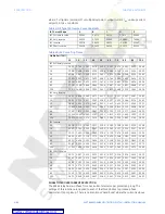
ANSI curves are derived from the following formula:
Eq. 13
where:T = trip time (seconds); M = multiplier value; I = input current; I
pu
= pickup current
setpoint; A, B, C, D, E = constants
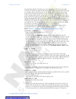
Table 5: ANSI Curve Constants
ANSI Curve Shape
A
B
C
D
E
ANSI Extremely Inverse
0.0399
0.2294
0.5000
3.0094
0.7222
ANSI Very Inverse
0.0615
0.7989
0.3400
–0.2840
4.0505
ANSI Normally Inverse
0.0274
2.2614
0.3000
–4.1899
9.1272
ANSI Moderately Inverse
0.1735
0.6791
0.8000
–0.0800
0.1271


