CHAPTER 6: SETPOINTS
S5 INPUTS/OUTPUTS
345 TRANSFORMER PROTECTION SYSTEM – INSTRUCTION MANUAL
6–133
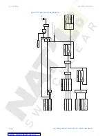
Figure 39: Relay 1 "TRIP" and Relay #2 "TRIP" logic diagram
TRIP
(Protection,
Controls)
T
rip
request
SETPOINT
(BREAKER
)
52b
CONT
ACT
Contact
input
SETPOINT
(BREAKER
)
52a
CONT
ACT
Contact
input
AND
OR
52b
contact
(Breaker
Open
=
1
)
AND
52a
contact
(Breaker
Close
=
1
)
Breaker
Open
OR
At
least
one
contact
programmed
AND
OR
TRIP
No
feedback
change
OR
timed
reset
SETPOINT
(BF
)
BF
FUNCTION
:
Disabled
=
0
Latched
Alarm
Alarm
BF
TIME
DELA
YS
SETPOINT
(B
F
)
RUN
OR
OR
OR
AND
AND
T
rip
Output
Seal
-I
n
time
SETPOINT
t
RST
AND
LED:
TRIP
OR
Local
Open
(Relay
Keypad
)
Remote
Open
Relay
(
Ready
=
1
)
RESET
(Relay
Keypad)
RESET
(Communications
)
RESET
(Input)
Breaker
Control
OR
LED
:
TRIP
AND
OR
timer
100
ms
RUN
OR
t
RST
SETPOINT
BLOCK
TRIP
RL
Y
Disbaled
=
0
(Selected
Input
,
O
N
=1
)
OR
timer
2
sec
LED:
BREAKER
OPEN
897775.cdr
TRIP
Operate
Output
Relay
1
TRIP
T
o
Breaker
Failure
(TRIP)


