CHAPTER 6: SETPOINTS
S3 PROTECTION
345 TRANSFORMER PROTECTION SYSTEM – INSTRUCTION MANUAL
6–73
Transformer
instantaneous
differential
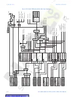
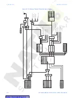
The 345 relay provides one Instantaneous Differential element per setpoint group.
Instantaneous Differential protection is not biased protection and operates in a fashion
similar to instantaneous overcurrent protection. Inputs to this protection are computed on
the basis of the relay per-phase differential currents. Operation occurs if the value of any of
the computed phase differential currents is above the instantaneous differential pickup
setting.
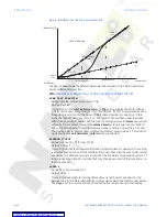
Instantaneous Differential protection is usually set to operate during high-fault current
situations, and if used, its pickup is set according to the following criteria:
•
The pickup setting (xCT) is selected to be higher than the maximum inrush current
during transformer energization
•
The pickup setting is set higher than the fault current for faults occuring outside the
zone of protection
•
The pickup setting is selected to be lower than the maximum fault current during
internal fault conditions.
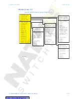
PATH:
SETPOINTS > S3 PROTECTION > S3 PROTECTION GROUP 1(2) > XFMR INST DIFF
INST DIFF FUNCTION
Range: Disabled, Latched Alarm, Alarm, Trip
Default: Disabled
The selection of the
Latched Alarm
,
Alarm
, or
Trip
setting enables the Instantaneous
Phase Differential function. The output relays #1 “R1 TRIP” and #2 “R2 TRIP” will operate,
when the
Trip
setting is selected, and the Instantaneous Differential protection is
operational. In this mode, the “ALARM” LED does not turn on. The “ALARM” LED will flash
under the instantaneous differential operating condition, with the function setting
selected as
Alarm
, and will self-reset, when the condition clears. If the
Latched Alarm
setting is selected, the “ALARM” LED will flash during the operating condition, and will
stay “ON” after the condition clears, until the reset command is initiated. The output
relays #1 “R1 TRIP” and #2 “R2 TRIP” will not operate if the
Latched Alarm
or
Alarm
setting is selected.
INST DIFF PICKUP
Range: 3.00 – 20.00 xCT in steps of 0.01 xCT
Default: 8.00xCT
This setting defines the pickup level of the differential current required for operation.
OUTPUT RELAY 3 to 6
Range: Do Not Operate, Operate
Default: Do Not Operate
Any, or all, of output relays 3 to 6 can be selected to operate upon instantaneous
Differential Protection operation. The selection of output relays operation is available no
matter whether the
Latched Alarm
,
Alarm
, or
Trip
function is selected.
INST DIFF BLOCK1/2/3
Range: Off, Contact Input 1 to 10, Virtual Input1 to 32, Remote Input 1 to 32, Logic
Elements1 to 16
Default: Off
Three blocking inputs are provided in the Percent Differential menu. When any of the
selected blocking inputs - Contact input, Virtual Input, or Remote Input - is turned on, the
XFMR INST DIFF function will be blocked.

