CHAPTER 6: SETPOINTS
S4 CONTROLS
345 TRANSFORMER PROTECTION SYSTEM – INSTRUCTION MANUAL
6–109
S4 Controls
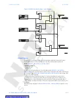
Figure 33: Controls menu
Change setpoint group
The 345 relay has two identical setpoint groups- Group 1 and Group 2 for all protection
elements. Switching between these two groups is available automatically by assigning an
input (contact, virtual, remote, logic element), or via communications.
Group 1 is the default setpoint group. The relay can automatically switch from Group 1
protections to Group 2 protections, and vice versa, by setting up the switching conditions
under “
Change Setpoint Group
”. Under some application conditions, such as an over-
current, or voltage element pick up, it may not be desirable to change setpoint groups. A
setpoint change can also be prevented if the breaker is open, so that a fault detected
before a reclosure will not cause a group change while the breaker is open. In such cases,
the user can set a condition under “BLK GROUP CHANGE”, where if asserted, the active
setpoint group will stay active, even if the input configured to switch to the other setpoint
group is asserted. For example if the active group was Group 1 at the time of a trip, the
breaker opens, and the input configured under “BLK GROUP CHANGE” is asserted, the relay
897767A1. cdr
S4 CONTROLS
CHANGE SETP GROUP
VIRTUAL INPUTS
LOGIC ELEMENTS
W1 BREAKER FAIL
W2 BREAKER FAIL
RESET
▼
S4 CHANGE SETP GROUP
SET GROUP 2 ACTIVE
BLK GROUP CHANGE
▼
S4 W1 BREAKER FAIL
BF FUNCTION
BF EXT INITIATE
BF TIME DELAY 1
2
OUTPUT RELAY 3
...
OUTPUT RELAY 6
BF CURRENT
BF TIME DELAY
▼
S4 LOGIC ELEMENT 1
LOGIC E1 NAME
LOGIC E1 ASSERTED
TRIGGER SOURCE 1
PICKUP TIME DELAY
DROPOUT TIME DELAY
RLY 1 TRIP W1 BKR
OUTPUT RELAY 3
...
OUTPUT RELAY 6
BLOCK 1
BLOCK 2
BLOCK 3
BLOCK LOGIC
LOGIC E1 FUNCTION
TRIGGER SOURCE 2
TRIGGER SOURCE 3
TRIGGER LOGIC
RLY 2 TRIP W2 BKR
▼
S4 VIRTUAL INPUTS
...
VIRTUAL INPUT 1
VIRTUAL INPUT 2
VIRTUAL INPUT 32
▼
S4 LOGIC ELEMENTS
...
LOGIC ELEMENT 1
LOGIC ELEMENT 2
LOGIC ELEMENT 3
LOGIC ELEMENT 4
LOGIC ELEMENT 16[8]
▼


