6–78
345 TRANSFORMER PROTECTION SYSTEM – INSTRUCTION MANUAL
S3 PROTECTION
CHAPTER 6: SETPOINTS
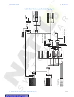
BLOCK 1/2/3
Range: Off, Contact Input 1 to 10, Virtual Input1 to 32, Remote Input 1 to 32, Logic
Elements1 to 16
Default: Off
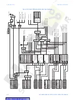
Three blocking inputs are provided in the Restricted Ground Fault menu. When any of the
selected blocking inputs - Contact input, Virtual Input, or Remote Input - is turned on, the
Restricted Ground Fault function will be blocked.
Example:
Transformer: 5MVA, 13.8kV/4.16kV, D/Yg1 type
R
g
= 10 ohms
Phase CTs: 800:5
Ground CT: 300:5
If
gnd (max)
= 4.16kV/(10 ohms *
√
3) = 240A - maximum ground fault current
To detect a ground fault on the Wye winding at 15% distance from the neutral point, the
relay shall detect ground differential current of:
I
gd
= (15x240)/100 = 36 A/800 = 0.045 x CT – PKP setting for the RGF protection
The transformer loading will be almost unaffected for ground faults close to the winding
neutral, so that the winding rated load can be used as a reference in defining the RGF
slope setting. The rated load for 4.16kV Wye winding is:
I
rated
= 5MVA/(4.16kV*
√
3) = 693 A
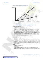
Slope setting, % = (36 A/693A)*100 = 5.1 %. Select 5% if the transformer is expected to run
most of the time at full load. If most of the time the transformer runs at lower than the
nominal loads, the slope setting can be set to higher value:
@ 70% load the slope setting would be: (36 / 485 A)*100 = 7%
@ 50% load the slope setting would be: (36 / 346 A)*100 = 10% \
@ 30% load the slope setting would be: (36 / 208 A)*100 = 17%
The ground current supervision feature and/or the RGF pickup time delay can be used if CT
saturation due to heavy external faults, is a concern.

