


6-2
469 Motor Management Relay
GE Power Management
6.1 MODBUS COMMUNICATIONS
6 COMMUNICATIONS
6
6.1.4 DATA PACKET FORMAT
A complete request/response sequence consists of the following bytes (transmitted as separate data frames):
•
SLAVE ADDRESS: This is the first byte of every transmission. This byte represents the user-assigned
address of the slave device that is to receive the message sent by the master. Each slave device must be
assigned a unique address and only the addressed slave will respond to a transmission that starts with its
address. In a master request transmission the SLAVE ADDRESS represents the address of the slave to
which the request is being sent. In a slave response transmission the SLAVE ADDRESS represents the
address of the slave that is sending the response. Note: A master transmission with a SLAVE ADDRESS
of 0 indicates a broadcast command. Broadcast commands can be used for specific functions.
•
FUNCTION CODE: This is the second byte of every transmission. Modbus defines function codes of 1 to
127. The 469 implements some of these functions. In a master request transmission the FUNCTION
CODE tells the slave what action to perform. In a slave response transmission if the FUNCTION CODE
sent from the slave is the same as the FUNCTION CODE sent from the master indicating the slave per-
formed the function as requested. If the high order bit of the FUNCTION CODE sent from the slave is a 1
(i.e. if the FUNCTION CODE is
>
127) then the slave did not perform the function as requested and is
sending an error or exception response.
•
DATA: This will be a variable number of bytes depending on the FUNCTION CODE. This may be Actual
Values, Setpoints, or addresses sent by the master to the slave or by the slave to the master. Data is sent
MSByte first followed by the LSByte.
•
CRC: This is a two byte error checking code. CRC is sent LSByte first followed by the MSByte. The RTU
version of Modbus includes a two byte CRC-16 (16-bit cyclic redundancy check) with every transmission.
The CRC-16 algorithm essentially treats the entire data stream (data bits only; start, stop and parity
ignored) as one continuous binary number. This number is first shifted left 16 bits and then divided by a
characteristic polynomial (11000000000000101B). The 16-bit remainder of the division is appended to the
end of the transmission, LSByte first. The resulting message including CRC, when divided by the same
polynomial at the receiver will give a zero remainder if no transmission errors have occurred.
If an 469 Modbus slave device receives a transmission in which an error is indicated by the CRC-16 calcu-
lation, the slave device will not respond to the transmission. A CRC-16 error indicates than one or more
bytes of the transmission were received incorrectly and thus the entire transmission should be ignored in
order to avoid the 469 performing any incorrect operation.
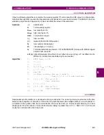
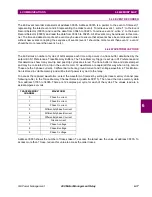
The CRC-16 calculation is an industry standard method used for error detection. An algorithm is included
here to assist programmers in situations where no standard CRC-16 calculation routines are available.
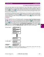
MASTER QUERY MESSAGE:
SLAVE ADDRESS:
(1 byte)
FUNCTION CODE:
(1 byte)
DATA:
(variable number of bytes depending on FUNCTION CODE)
CRC:
(2 bytes)
SLAVE RESPONSE MESSAGE:
SLAVE ADDRESS:
(1 byte)
FUNCTION CODE:
(1 byte)
DATA:
(variable number of bytes depending on FUNCTION CODE)
CRC:
(2 bytes)