5-12
469 Motor Management Relay
GE Power Management
5.3 A2 METERING DATA
5 ACTUAL VALUES
5
5.3.5 POWER METERING
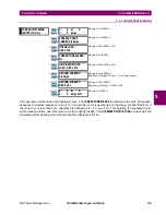
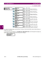
The values for power metering and 3-phase total power quantities are displayed here. Watthours and varhours
can also be seen here.
An induction motor by convention consumes Watts and vars (+Watts and +vars). A synchro-
nous motor can generate vars (–vars) and feed them back to the power system.
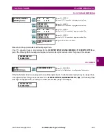
If the
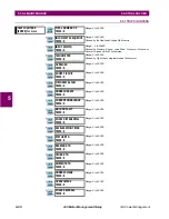
S2 SYSTEM SETUP \ VOLTAGE SENSING \ VOLTAGE TRANSFORMER RATIO
setpoint is not programmed, the fol-
lowing flash message appears when an attempt is made to enter this group of messages.
Real Power (hp) is converted directly from Real Power (kW). This display-only value is not
used for protection functions. This message will not display more than 65535 hp regardless of
the actual kW that are being metered.
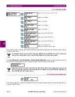
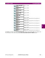
5.3.6 TORQUE ALARM MESSAGE
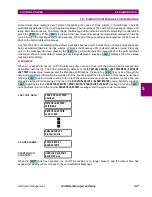
This message appears in the Alarm Status Event Record (if programmed) and as a display message when an
overtorque alarm occurs.
y
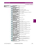
POWER METERING
y
[ENTER] for more
POWER FACTOR:
0.00
Range: 0.01 to 0.99 Lead or Lag, 0.00, 1.00
REAL POWER:
0 kW
Range: 0 to ±99999 kW
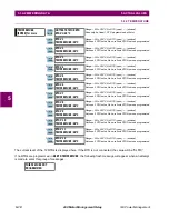
REAL POWER:
O hp
Range: 0 to 65535 hp
REACTIVE POWER:
0 kvar
Range: 0 to ±99999 kvar
APPARENT POWER:
0 kVA
Range: 0 to 65535 kVA
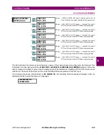
POSITIVE WATTHOURS:
0.000 MWh
Range: 0.000 to 999999.999 MWh
POSITIVE VARHOURS:
0.000 Mvarh
Range: 0.000 to 999999.999 Mvarh
NEGATIVE VARHOURS:
0.000 Mvarh
Range: 0.000 to 999999.999 Mvarh
TORQUE:
000.0 Nm
Range: 0.00 to 999999.9 Nm
Seen only if Torque Metering is enabled
THIS FEATURE NOT
PROGRAMMED
TORQUE
ALARM: 0.00
ENTER
ESCAPE
ð
ð
MESSAGE
ESCAPE
MESSAGE
ESCAPE
MESSAGE
ESCAPE
MESSAGE
ESCAPE
MESSAGE
ESCAPE
MESSAGE
ESCAPE
MESSAGE
ESCAPE
MESSAGE
ESCAPE
NOTE
NOTE
ENTER
ESCAPE
ð
ð


