


GE Power Management
469 Motor Management Relay
4-85
4 SETPOINT PROGRAMMING
4.14 S13 469 TESTING
4
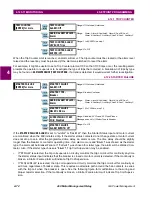
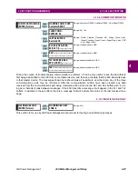
4.14.3 FAULT SETUP
The values entered under Fault Values will be substituted for the measured values in the 469 when the simula-
tion mode is
"Simulate Fault"
.
y
FAULT SETUP
y
[ENTER] for more
FAULT CURRENT
PHASE A: 0.00 x CT
Range: 0.00 to 20.00 x CT, step 0.01
FAULT CURRENT
PHASE B: 0.00 x CT
Range: 0.00 to 20.00 x CT, step 0.01
FAULT CURRENT
PHASE C: 0.00 x CT
Range: 0.00 to 20.00 x CT, step 0.01
FAULT GROUND
CURRENT: 0.0 A
Range: 0.0 to 5000.0 A, step 0.1
FAULT VOLTAGES
VLINE: 1.00 x RATED
Range: 0.00 to 1.10 x RATED, step 0.01
FAULT CURRENT
LAGS VOLTAGE: 0°
Range: 0 to 359°, step 1
FAULT DIFF AMPS
IDIFF: 0.00 x CT
Range: 0.00 to 1.10 x RATED, step 0.01
FAULT STATOR
RTD TEMP: 40°C
Range: –50 to 250°C, step 1
FAULT BEARING
RTD TEMP: 40°C
Range: –50 to 250°C, step 1
FAULT OTHER
RTD TEMP: 40°C
Range: –50 to 250°C, step 1
FAULT AMBIENT
RTD TEMP: 40°C
Range: –50 to 250°C, step 1
FAULT SYSTEM
FREQUENCY: 60.0 Hz
Range: 45.0 to 70.0 Hz, step 0.1
FAULT ANALOG
INPUT 1: 0%
Range: 0 to 100%, step 1
FAULT ANALOG
INPUT 2: 0%
Range: 0 to 100%, step 1
FAULT ANALOG
INPUT 3: 0%
Range: 0 to 100%, step 1
FAULT ANALOG
INPUT 4: 0%
Range: 0 to 100%, step 1
ENTER
ESCAPE
ð
ð
MESSAGE
ESCAPE
MESSAGE
ESCAPE
MESSAGE
ESCAPE
MESSAGE
ESCAPE
MESSAGE
ESCAPE
MESSAGE
ESCAPE
MESSAGE
ESCAPE
MESSAGE
ESCAPE
MESSAGE
ESCAPE
MESSAGE
ESCAPE
MESSAGE
ESCAPE
MESSAGE
ESCAPE
MESSAGE
ESCAPE
MESSAGE
ESCAPE
MESSAGE
ESCAPE