


GE Power Management
469 Motor Management Relay
5-15
5 ACTUAL VALUES
5.3 A2 METERING DATA
5
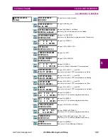
5.3.9 PHASORS
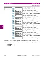
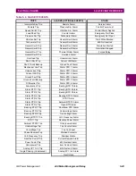
To aid in wiring, the tables on the following page can be used to determine if VTs and CTs are on the correct
phases and that their polarity is correct. Problems arising from incorrect wiring are extremely high unbalance
levels (CTs) or erroneous power readings (CTs and VTs) or phase reversal trips (VTs).
To correct wiring, simply start the motor and record the phasors. Using the tables below along with recorded
phasors, system rotation, VT connection type, and motor power factor the correct phasors can be determined.
Note that the phase angle for Va (Vab if delta) is always assumed to be 0° and is the reference for all angle
measurements.
Common problems include: Phase currents 180° from proper location (CT polarity reversed)
Phase currents or voltages 120 or 240° out (CT/VT on wrong phase)
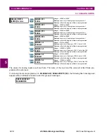
y
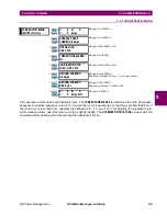
PHASORS
y
[ENTER] for more
Va PHASOR
0.0% AT 0°Lag
Vb PHASOR
0.0% AT 0°Lag
Vc PHASOR
0.0% AT 0°Lag
Ia PHASOR
0.0% AT 0°Lag
Ib PHASOR
0.0% AT 0°Lag
Ic PHASOR
0.0% AT 0°Lag
ENTER
ESCAPE
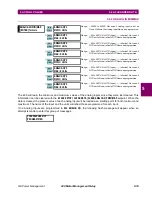
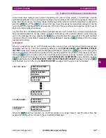
ð
ð
MESSAGE
ESCAPE
MESSAGE
ESCAPE
MESSAGE
ESCAPE
MESSAGE
ESCAPE
MESSAGE
ESCAPE