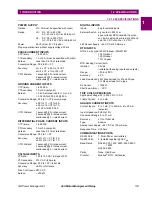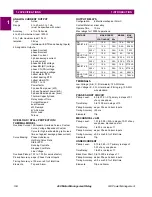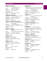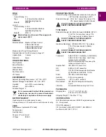
1-4
469 Motor Management Relay
GE Power Management
1.1 OVERVIEW
1 INTRODUCTION
1
1.1.2 ORDER INFORMATION
All 469 features are standard; there are no options. The phase CT secondaries, control power, and analog out-
put range must be specified at the time of order. The 469 differential CT inputs are field programmable for CTs
with 1 A or 5 A secondaries. There are two ground CT inputs, one for the GE Power Management 50:0.025
core balance CT and one for a ground CT with a 1 A or 5 A secondary, also field programmable. The VT inputs
will accommodate VTs in either a delta or wye configuration. The output relays are always non-failsafe with the
exception of the service relay. The 469PC software is provided with each unit. A metal demo case may be
ordered for demonstration or testing purposes.
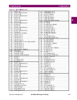
Figure 1–3: 469 ORDER CODES
Additional accessories are listed in the following section.
1.1.3 OTHER ACCESSORIES
•
469PC Software:
Provided free with each relay
•
DEMO:
Metal Carry Case in which 469 unit may be mounted
•
SR 19-1 PANEL:
Single cutout 19" panel
•
SR 19-2 PANEL:
Dual cutout 19" panel
•
SCI MODULE:
RS232 to RS485 converter box designed for harsh industrial environments
•
Phase CT:
50, 75, 100, 150, 200, 250, 300, 350, 400, 500, 600, 750, 1000
•
HGF3, HGF5, HGF8:
For sensitive ground detection on high resistance grounded systems.
•
469 1" Collar:
For shallow switchgear, reduces the depth of the relay by 1 #3/8"
•
469 3" Collar:
For shallow switchgear, reduces the depth of the relay by 3"
•
Optional Mounting Kit:
Additional mounting support 1819-0030
469
469
Basic unit
P1
P5
1A phase CT secondaries
5A phase CT secondaries
LO
HI
DC: 25-60 V; AC: 20-48 V @ 48-62 Hz
DC: 90-300 V; AC: 70-265 V @ 48-62 Hz
A1
A20
0-1 mA analog outputs
4-20 mA analog outputs
*
* *


