Lullaby
TM
Warmer 2042376-001 Rev G ©2012 General Electric Company. All rights reserved. 51
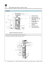
5.8.2
Mounting the Monitor /Instrument Tray
Illustration
Description
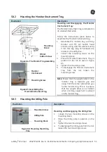
Figure 64:
The Monitor Tray Assembly
Figure 65:
Assembling the
Monitor/Instrument Tray
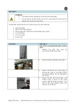
Mounting and Disengaging the Monitor
/Instrument Tray:
The Monitor/Instrument tray is delivered in
an unassembled state.
Follow the instructions given below to
assemble the Monitor/Instrument tray:
1.
Assemble the monitor tray with tray
bracket with M5 skt button head
screws, spring and flat washers using
3 mm Hex key. (Qty 4). Fasteners are
located in the utility box.
2.
Loosen the mounting screw on the
mounting block.
3.
Place the Monitor/Instrument Tray in
position on the rail as seen in Figure
65.
4.
Tighten the mounting screw.
5.
To disengage the Monitor /Instrument
Tray from the rail, loosen the
mounting screw.
Note
: Ensure that the weight label on the
monitor tray is towards you and
away from the center pillar when you
fix the monitor tray. This is to ensure
that the weight label is not hidden
when ancillary equipment is placed
on the monitor tray.
5.8.3
Mounting the Utility Pole
Illustration
Description
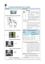
Figure 66:
Mounting the Utility
Pole
Mounting and Disengaging the Utility Pole:
1.
Loosen the two mounting screws on the
mounting block.
2.
Place the Utility pole in position on the
rail.
3.
Tighten the two mounting screws.
4.
To disengage the Utility pole from the rail,
loosen the two mounting screws.
Monitor
/Instrument
Tray
Mounting Screw
M5 Skt
button Screw
Mounting
Block
Mounting Screw
Utility Pole
Mounting Block
Summary of Contents for Lullaby Warmer
Page 12: ...This page is left blank intentionally ...
Page 139: ...LullabyTM Warmer 2042376 001 Rev G 2012 General Electric Company All rights reserved 113 ...
Page 140: ...114 2042376 001 Rev G 2012 General Electric Company All rights reserved LullabyTM Warmer ...
Page 150: ...124 2042376 001 Rev G 2012 General Electric Company All rights reserved LullabyTM Warmer ...

