6. Replace the Device in the cassette as
described in section 1.3.3.2
7. If needed, a clearly marked grounding point is
provided on both sides of the cassette.
1.3.3.1 Circuit Breaker Removal from the
Cassette
Lift the circuit breaker clear of the draw out
support slides using the hand grips on either
side (Fig. 1.3 page 1.3-00) or the lifting eyes (Fig.
1.4).
1.3.3.2 Circuit breaker Mounting in the
Cassette.
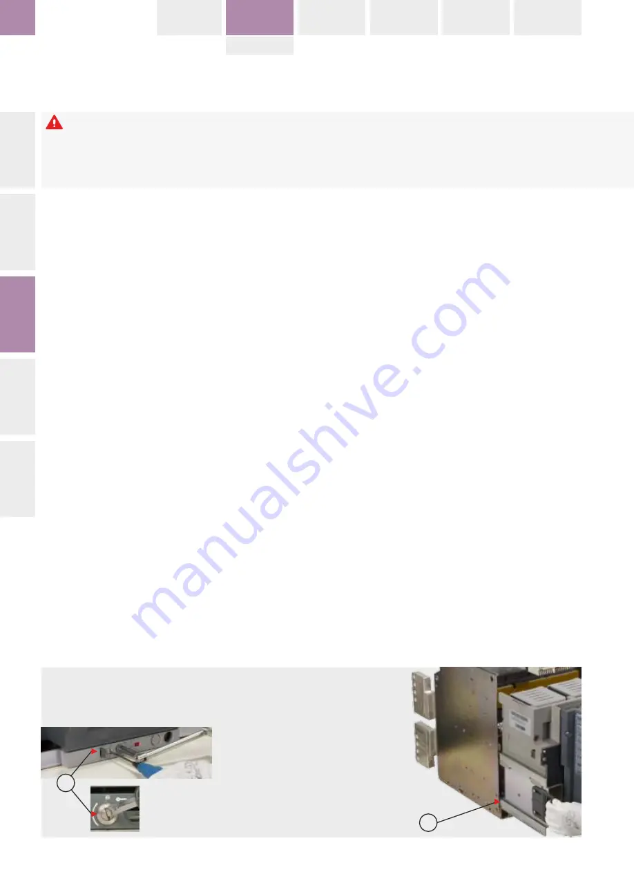
1. Take out the racking handle from the storage
tube, with a screw driver turn the racking handle
shutter drive Anti-clockwise and insert handle
then rotate the Handle in Anti-clockwise till it
gets a positive stop. Ensure cassette position
indicator shows DISCONNECT and racking
handle is disengaged.
2. Fully extend the cassette draw out support
slides until they reach a positive stop.
3. Switch OFF the breaker by pressing OFF push
button fig. 1.7a
4. Lower the device on to the drawout support
slides making use of the lifting methods
described here. Carefully verify that the pockets
in the Housings of this device are correctly
engaged on the slides.
5. Push the circuit breaker into the cassette
equally on both right and left sides until it
reaches a positive stop. Ensure the position of
rails are equal on Both sides. The circuit breaker
is now in the DISCONNECTED position.
6. Take out the racking handle from the storage
location fig. 1.7b
7. With a screwdriver, turn the racking handle
shutter drive clockwise (Fig. 1.5c), insert the
racking handle and rotate clockwise to rack the
circuit breaker into the cassette. As the breaker
approaches the TEST position check the
alignment of the fixed and moving parts of the
secondary circuit isolating contacts.
8. Keep on rotating the racking handle
clockwise. The racking drive indicator will move
from the DISCONNECTED to TEST and finally to
Fig. 1.5b: Slides
..on which the breaker rollers must engage
..no qual os rolamentos to disjuntor devem engrenar
..na których powinny być osadzone rolki wyłącznika
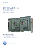
Fig. 1.5c: Racking Screw Location
A) Racking Screw Shutter Drive
A) Obturador da manivela de extração
A) Lokalizacja śruby napędu wsuwania
Please ensure that the breaker is placed in
tripped position, that the operation indicator
shows OFF and that the mechanisms springs
are fully discharged.
DANGER | PERIGO | NIEBEZPIECZEŃSTWO
Wyłącznik powinien być otwarty (przez
wyzwolenie), wskaźnik stanu powinien
wskazywać OFF (WYŁ), sprężyny mechanizmu
napędowego powinny być całkowicie luźne
(rozbrojenie).
INTR
O
SPECIFICA
TION
INST
ALL
A
TION
OPER
A
TION
TRIP UNIT
LOCKS
EntelliGuard L
INTRO
BREAKER
ACCESSORIES
TESTS
APPENDIX
TRIP UNIT
1.3-06
montagem serem completamente apertados.
6. Insira o aparelho no chassi, como descrito na
seção 1.3.3.2
7. Se necessário, está disponível em ambos os
lados do chassi um ponto de ligação à terra.
1.3.3.1 Remoção do Disjuntor da Chassi
Levante claramente o disjuntor dos suportes
extensíveis de extração, usando as pegas
manuais de cada lado (Fig. 1.3) ou os olhais de
içamento (Fig. 1.4).
1.3.3.2 Montagem do Disjuntor no Chassi.
1. Retire a manivela de extração do tubo de
armazenamento, com uma chave de fenda gire
o obturador da manivela de extração no sentido
anti-horário, insira a manivela e então gire a
manivela no sentido anti-horário até que o
mesmo seja forçado a parar. Confirme que o
indicador de posição do chassi mostra
DESCONECTADO e que a manivela de extração
esteja desengatada.
2. Estenda totalmente os suportes de extração
do chassi, até que eles não saiam mais.
3. Desligue o disjuntor pressionando o botão
OFF fig. 1.7a
4. Desça o dispositivo nos trilhos do suporte
extraível utilizando os métodos de içamento
descritos aqui. Cuidadosamente verifique que
os encaixes deste dispositivo estão
corretamente engatados nos trilhos.
5. Empurre o disjuntor para dentro do chassi
igualmente pela direita e esquerda até que o
mesmo seja forçado a parar. Confirme que a
posição dos trilhos é igual em ambos os lados. O
disjuntor está agora na posição
DESCONECTADO.
6. Retire a manivela de extração do seu local de
armazenamento fig. 1.7b
7. Com uma chave de fenda, gire o obturador da
manivela de extração no sentido horário (fig.
1.5c), insira a manivela de extração e gire no
sentido horário para inserir o disjuntor no chassi.
A medida que o disjuntor se aproxima da
posição TESTE, confirme o alinhamento das
partes fixas e móveis dos contatos de
6. Wsunąć aparat w podstawę w sposób
opisany w rozdziale 1.3.3.2
7. W razie potrzeby podłączyć uziemienie w
punktach znajdujących się po obu stronach
podstawy.
1.3.3.1 Wyjmowanie wyłącznika z podstawy
Unieść wyłącznik i wyciągnąć z prowadnic
podstawy używając uchwytów po obu stronach
(Fot. 1.3) lub uchwytów transportowych (Fot.
1.4).
1.3.3.2 Wkładanie wyłącznika w podstawę
1. Wyjąć korbę napędu z opakowania, za
pomocą wkrętaka obrócić wkręt przesuwający
przesłonę otworu korby, przeciwnie do kierunkiu
wskazówek zegara, włożyć korbę, potem
obracać przeciwnie do ruchu wskazówek zegara
aż do zatrzymania. Upewnić się, że wskaźnik
położenia w podstawie jest w położeniu
ODŁĄCZONY i korba napędu jest wyjęta.
2. Całkowicie wysunąć prowadnice wsporcze
podstawy, aż do zatrzymania.
3. Wyłączyć wyłącznik przez naciśnięcie
przycisku OFF, fot. 1.7a
4. Osadzić aparat na prowadnicach wsporczych
podstawy użyć urządzeń i metod opisanych w
tej instrukcji. Ostrożnie sprawdzić czy kieszenie
w obudowach aparatu są prawidłowo
osadzone na prowadnicach.
5. Pchać równomiernie prawo/lewo wyłącznik
na prowadnicach w podstawę aż do
zatrzymania. Dopilnować aby pozycja na
szynach była jednakowa z obu ston. Wyłącznik
jest teraz w położeniu ODŁĄCZONY.
6. Wyjąć korbę z mechanizmu wsuwania, fot.
1.7b
7. Używając wkrętaka obrócić wkręt
przesuwający przesłonę otworu korby, zgodnie z
kierunkiem wskazówek zegara (fot . 1.7), włożyć
korbę i obracać zgodnie z kierunkiem
wskazówek zegara, aby wsunąć wyłącznik w
podstawę.
Gdy wyłącznik zbliża się do położenia PRÓBA
sprawdzić wzajemne ustawienie i dopasowanie
części stałej i ruchomej przyłączy obwodów
Por favor assegure-se que o disjuntor é
colocado na posição disparado, que o indicador
de posição indica OFF e que os mecanismos de
mola estão completamente descarregados.
Enquanto elevado, não toque nos contatos de
isolamento do disjuntor.
A
A


