Installation Procedures
2-40
560-0982-00 Rev D
Apollo CNX80 Installation Manual
Once the antenna mounting position has been prepared, route the coax cable from the antenna to the
CNX80. Proper selection of coax cable and assembly of connectors is critical to GPS signal performance.
The cable loss from the GPS antenna shall not be greater than 7 dB. If SatCom is installed on the aircraft,
the cable loss shall be 3 dB minimum to ensure proper interference rejection from SatCom. The coaxial
connectors and adapters, such as TNC to BNC, add additional loss to the cable and should be considered
when computing the cable loss. A typical loss of 0.2 dB can be used for each connection. The typical cable
loss for 20 feet of RG-142B coax with a connector one each end is 4 dB.
During the post-installation checkout, susceptibility to harmonics of VHF comm transmitters will be
evaluated. If problems arise, then better isolation, or distance, may be required between the GPS and comm
antennas, or a 1575.42 MHz notch filter may be installed in series with the antenna coax of the VHF comm
transceiver to reduce or eliminate the harmonic interference. A notch filter for this use (part #162-1059) is
available from Garmin AT.
NOTE
CNX80 performance has been verified in typical installations and has not shown problems
of the built-in comm interfering with the GPS when installed according to the
recommended installation guidelines.
If a VHF comm transmitter causes problems with the GPS on the selected frequencies as listed in the post-
installation checkout, the problem may be due to the ELT. This can be verified by disconnecting the ELT
antenna coax at the ELT unit. If the ELT is found to cause the problem, then contact the ELT
manufacturer or replace the ELT.
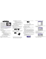
Figure 2-11 - Rear Coax Connector Assembly
2.9.3 NAV
A
NTENNA
The NAV antenna is a standard 50
Ω
horizontally polarized NAV/VOR/Localizer/Glideslope antenna that
receives VOR frequencies between 108 and 117.95 MHz, and localizer frequencies between 108 and 112
MHz, and glideslope information between 328.6 and 335.4 MHz. Follow the antenna manufacturer’s
installation instructions for mounting antennas. The Nav antenna should be mounted as far apart as
Summary of Contents for Apollo CNX80
Page 1: ...Apollo CNX80 Installation Manual September 2003 560 0982 00 Rev D...
Page 10: ...Table of Contents viii 560 0982 00 Rev D Apollo CNX80 Installation Manual NOTES...
Page 30: ...General Information 1 20 560 0982 00 Rev D Apollo CNX80 Installation Manual NOTES...
Page 114: ...Periodic Maintenance 6 2 560 0982 00 Rev D Apollo CNX80 Installation Manual NOTES...
Page 134: ...Appendix D Interconnect Diagrams D 2 560 0982 00 Rev D Apollo CNX80 Installation Manual NOTES...
Page 167: ......
Page 168: ......


