


64
Via Leonardo da Vinci, 32/B
36034 Malo (VI) Italia
Operation and maintenance manual
Rev. 01/18-GB
TZ FIBER 540E / 630E / Conveyor-E
The grease contained in the hydraulic crawler is
under pressure, so do not loosen the greasing valve
(1 Fig. 17) more than a turn. If the valve is too loose,
it’s likely to be expelled under the effect of the pres-
sure of the grease, thus seriously endangering the
safety of the operator. Be careful not to loosen ever
the nipple (2 Fig. 17).
When gravel or mud are stuck between the toothed
wheel and the track links, remove them before losing.
It is abnormal if the track remains tensed after turn-
ing the valve counter-clockwise or if the track is still
loose after putting the grease into the nipple. In any
case, avoid removing the tracks or disassembling
the track tensioner cylinder because the pressure
of the grease inside the track tensioner cylinder is
very dangerous.
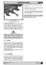
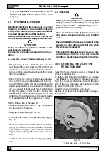
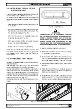
5.5.4 DISASSEMBLYING THE TRACKS
The tracks used in the «TZ FIBER» excavator have
a structure with steel core and rubber coating (Fig.
19). The sculptures are used to provide stability
when driving on soft ground.
These are located at the bottom resting on the
ground, while the guides of the wheel located inside
the track prevent the track to get out of the guide
rollers.
Improper use of the machine and use the machine
on stony and uneven surfaces lead to a premature
wear and tear of the tracks.
Should it be necessary to replace the tracks, pro-
ceed as follows.
After bringing the machine on a firm and leveled
surface, lift the machine in safety conditions placing
well stable supports under the under-trolley frame
able to support the assembly.
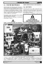
1) Remove the screws and the lid (3 Fig. 17) to
access the adjustment.
2) To loosen the track, slowly unscrew the valve (1
Fig. 17) counterclockwise not more than a turn. A
turn of the valve is sufficient to loosen the track.
The grease contained in the hydraulic cylinder is
under pressure, thus avoid loosen the greasing
valve (1 Fig. 17) for more than a turn. If the valve
is loosened too much, there is the risk of being
expelled under the effect of grease pressure,
seriously endangering the safety of the operator.
Be careful not to loosen the nipple (2 Fig. 17).
If gravel or mud are stuck between the toothed
wheel and the track links, remove them before
losing.
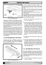
4) If the grease does not start to drain, slowly rotate
the track.
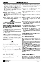
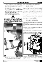
5) Place three steel tubes (4 Fig. 18) within the track
in the space between the rollers. Rotate the driv-
ing wheel in reverse (5 Fig. 18) so that the steel
pipes proceed with the track and place between
the tensioning wheel and it. Do strength side (6
Fig. 18) to slide the track and release it from the
track tensioning wheel.
5.5.5 ASSEMBLYING THE TRACKS
Also for the installation of the track, it is necessary
to bring the machine on a solid and flat surface, thus
lift the machine safely putting very stable supports
under the under-trolley frame able to support the
assembly and proceed with the assembly opera-
tions of the track.
1) Check that the grease contained in the hydraulic
cylinder is removed.
Fig. 20 - Dismantling track
Fig. 19 - Structure track
ROPES
STEEL
STEEL CORE
SCULPTURE
WHEEL SIDE
GEAR WHEEL
HOLE


