


52
Via Leonardo da Vinci, 32/B
36034 Malo (VI) Italia
Operation and maintenance manual
Rev. 01/18-GB
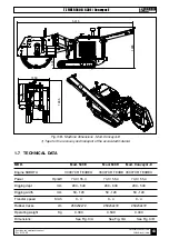
TZ FIBER 540E / 630E / Conveyor-E
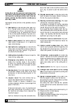
DANGER
During the work, the operator must always bear
the remote control in the shoulder strap and must
not leave the working machine more than ten
meters and the machine shall be continuously
and fully visible.
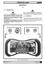
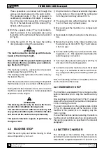
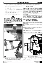
Description of the controls on the portable console
(Fig. 6):
1) Start button (on the left side of the radio con-
trol). Pressed (after turning the battery-dis-
connecting lever 10 Fig. 7 and positioned on
«I» the switch 2 Fig. 6), activates the consent
to the communication between the radio con-
trol and the receiver located inside the motor
bonnet.
2) Radio control switch. This switch starts the
radio control. Positioned on «I» it inserts the
radio control battery.
3) Start button for cutting disc (on the left side
of the radio control). When pressed, starts the
cutting disc (only if the «speed» 7 Fig. 6 knob
is turned to the minimum).
4) Cutting disc stop button. Pressed, stops the
motion of the cutting disk.
5) Emergency stop button. By pressing this
button the machine stops in the position
in which it is located and the various func-
tions are disabled. Only the engine remains
switched on.
6) Steering knob. This knob adjusts the speed
of one track relative to the other. To be used
exclusively on disconnected grounds or for
small turns.
7) «Speed» knob. This knob controls the hy-
draulic flow adjustment to the two tracks.
Under forward or reverse conditions, this
command adjusts the flow in percentage that
goes to the tracks.
If the knob is turned to «min», the machine will
slow down until it stops. If you turn to «max»,
the machine will always move towards the
maximum speed.
Set it on minimum to have the connection be-
tween the radio control and the receiver (but-
ton 1 Fig. 7) and/or to start the button disk 3
Fig. 7.
8) Throttle motor knob. Turning the knob to the
right increases the engine speed. Turning to
the left, the engine decelerates.
9) Steering control lever (steering). This lever
controls the continuous steering.
In conditions of forward or reverse, operating
on this lever decreases the percentage of hy-
draulic flow going to the right or left track.
If you push the lever towards "left", the ma-
chine will limit the flow to the left track by turn-
ing it to the left. If you push the lever towards
«right», the machine will limit the flow to the
right track by turning it to the right.
10) Forward or reverse control lever: By push-
ing the lever forward the machine moves for-
ward, backwards.
11) Control switch (cutting disc). Disc lifting
control: by moving the switch forward the cut-
ting blade with its structure rises, moving it to-
wards the operator, the disk is lowered.
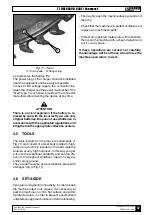
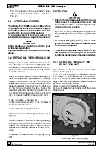
12) «Protection» control switch. It controls the
ascent / descent of the disc protection bulk-
heads thus determining the depth of the exca-
vation, which can be detected by the gradu-
ated scale visible next to the cutting disc (1
Fig. 8).
13) Cleaner switch.
Start the cleaner (if present).
14) Left/right side shift switch on the cutting
disc. It must only be used with the cutting disc
raised and out of ground.
15) Speed command switch. This switch con-
trols the speed in work and in the transfer.
By pushing the switch forward (hare symbol),
the machine moves in transfer.
By pulling the switch towards the operator
(turtle symbol) the machine advances in work-
ing speed.
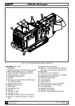
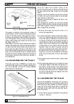
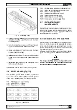
Description of the controls on the machine (Fig. 7):
1) Engine function control display.
2) Engine warning lights.
3) Water temperature gauge of the cooling circuit.
4) Engine working hours meter.


