


55
TZ FIBER 540E / 630E / Conveyor-E
Via Leonardo da Vinci, 32/B
36034 Malo (VI) Italia
Operation and maintenance manual
Rev. 01/18-GB
the maneuvers that are being executed, thereby
resulting in a dangerous situation.
If the work is suspended, albeit briefly, the control
unit must be turned off and the ignition key must
be removed from the transmitter, to prevent its
use by unauthorized persons.
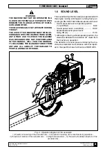
ATTENTION
After having found that:
- The machine is in perfect running order;
- The engine oil level is correct. Read what
shown in the instruction manual attached;
- All guards are intact and in their place;
- The hydraulic oil in the tank of the machine is
at the right level (trought the oil control window
16 Fig. 1/A) and of the type recommended;
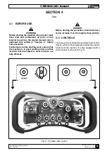
- The diesel fuel in the tank is at the right level
(see tabel on display Fig. 7);
- All parts subject to wear and tear are in per-
fect working order, in particular, in the state
of wear of the tools.
Following the safety instructions in this manual,
you can start operating.
After removal of any foreign particles within the
range of the machine, and bounded the operational
area, proceed with the start-up in the following way:
1) Rotate the battery-disconnecting lever vertically
(10 Fig. 7), with this operation the consent is
given to the battery to power the electrical cir-
cuit.
Check that the emergency stop button (14 Fig.
7) is off and there are no other active com-
mands.
2) Turn the starter key to the right at the first click
(13 Fig. 7) and wait until the lights on the display
(2 Fig. 7) except the «N» and «P» go out.
The orange flashing light comes on (12 Fig. 7).
3) Turn the start key further to the right (13 Fig. 7).
Once the engine has started, release the starter
key.
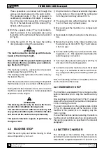
4) Check that the knob (7 Fig. 6) «Speed» and the
knob (8 Fig. 6) «accelerator» are in the mini-
mum position.
5) Turn the switch (2 Fig. 6) to position «1».
6) Press the start button (1 Fig. 6). With this opera-
tion the radio control is enabled and wait a few
seconds so that the receiver performs the con-
trol tests. When the radio control is connected
«N» and «P» switch off.
ATTENTION
After start-up, perform vacuum movements to
verify the correct operation of each command. If
you should notice any abnormality, stop the en-
gine immediately and call the Security Manager.
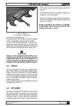
7) With the operating machine started, make the
desired settings of the disc: number of revolu-
tions and height of the bulkhead that determines
the depth of excavation.
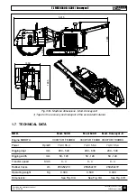
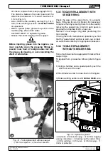
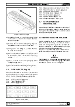
Fig. 8 - Lifting/lowering the bulkhead
1) Graduated scale in centimeters. - 2) Level line
indicating the depth of excavation. - 3) Sledges.
2
1
3


