


40
Via Leonardo da Vinci, 32/B
36034 Malo (VI) Italia
Operation and maintenance manual
Rev. 01/18-GB
TZ FIBER 540E / 630E / Conveyor-E
26
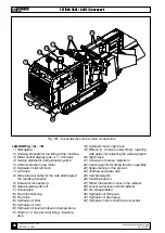
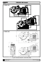
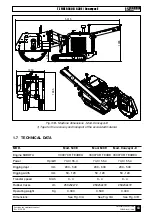
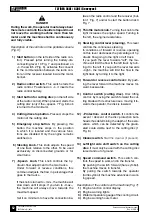
Fig. 1/B - Excavator disc and its main components
12
LEGEND Fig. 1/A - 1/B
1) Nameplate.
2) Hooking brackets for the lifting of the machine.
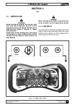
3) Motor control display (see 4.1.1 Controls).
4) Service distributor and hydraulic system.
5) Carter protection area motor.
6) Hydraulic motor left track.
7) Left track.
8) Slots (one per side) for the side discharge of
the resulting material
9) Excavator disk bearing.
10) Special steel peak tool.
11) Exaust pipe.
12) Fuel tank filler cap.
13) Fuel tank.
14) Hydraulic oil filter.
15) Hydraulic oil tank.
16) Hydraulic oil level window and temperature.
17) Piston (n. 2 one per side) lifting / lowering
disk.
13
18) Hydraulic motor right track.
19) Pistons (n. 2 one per side) lifting / lowering
side plates for adjusting the working depth.
20) Right track.
21) Conveyor of coarse material is.
22) Hooking points for lifting the disc assembly.
23) Slides resting on the ground.
24) Toothed excavator disc.
25) Counterweights.
26) Flashing beacon.
27) Water introduction cover in the radiator.
28) Louver water level control radiator.
29) Air intake prefilter.
30) Hydraulic oil filling cap.
31) Hydraulic oil drain plug.
32) Hydraulic motor control disc excavator.
29
11
27
28
2
3
25
22


